-
Notifications
You must be signed in to change notification settings - Fork 2
Tutorial
Since the Max sample file covers the most amount of information so far, we recommended that you start with downloading Max and testing the following patch: STEP400_proto_r4.maxpat
- openFrameworks Contribution of @niimi
- Unity Contribution of @niimi
- Touch Designer Contribution of @loveandsheep
First of all, connect the PC and STEP400 with a Ethernet cable. If the PC does not have an Ethernet port, you will need to use a USB-Ethernet converter.
To simplify this tutorial, we will assume that the PC and the board are connected 1:1 to a LAN. You can of course also go through a network switch instead.
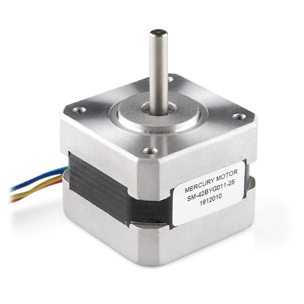
The type of stepper motor that can be used with STEP400 is a "bipolar" one. Power supply capacity and settings will vary depending on what motor is used. A good example of easily available motor is MERCURY MOTOR's SM-42BYG011-25. It can be purchased at the following sources, among others:
Here, we will use this motor as an example for specific setting values. Click here for information about how to connect the board to a motor and to a power supply.
The STEP400's power connector is designed to connect to a large-capacity power supply, but when you are running a small motor, it is convenient to connect to an AC adapter using the conversion connector shown in the picture below. This connector is available at electronic parts stores or Amazon. If you want to run a single motor in the example above, the AC adapter's capacity of 24V1A is sufficient.
In this photo, the terminals are crimped at both ends, but they can also be used with both ends stripped and just soldered.
You can turn on the power after the DIP switches described below have been set.
You have the possibility to change your network settings using the Configuration Tool (HTML+JavaScript) to generate a configuration file, which can then be written onto a microSD card. In this tutorial however, we will use the default settings, so you can just leave the microSD slot empty.
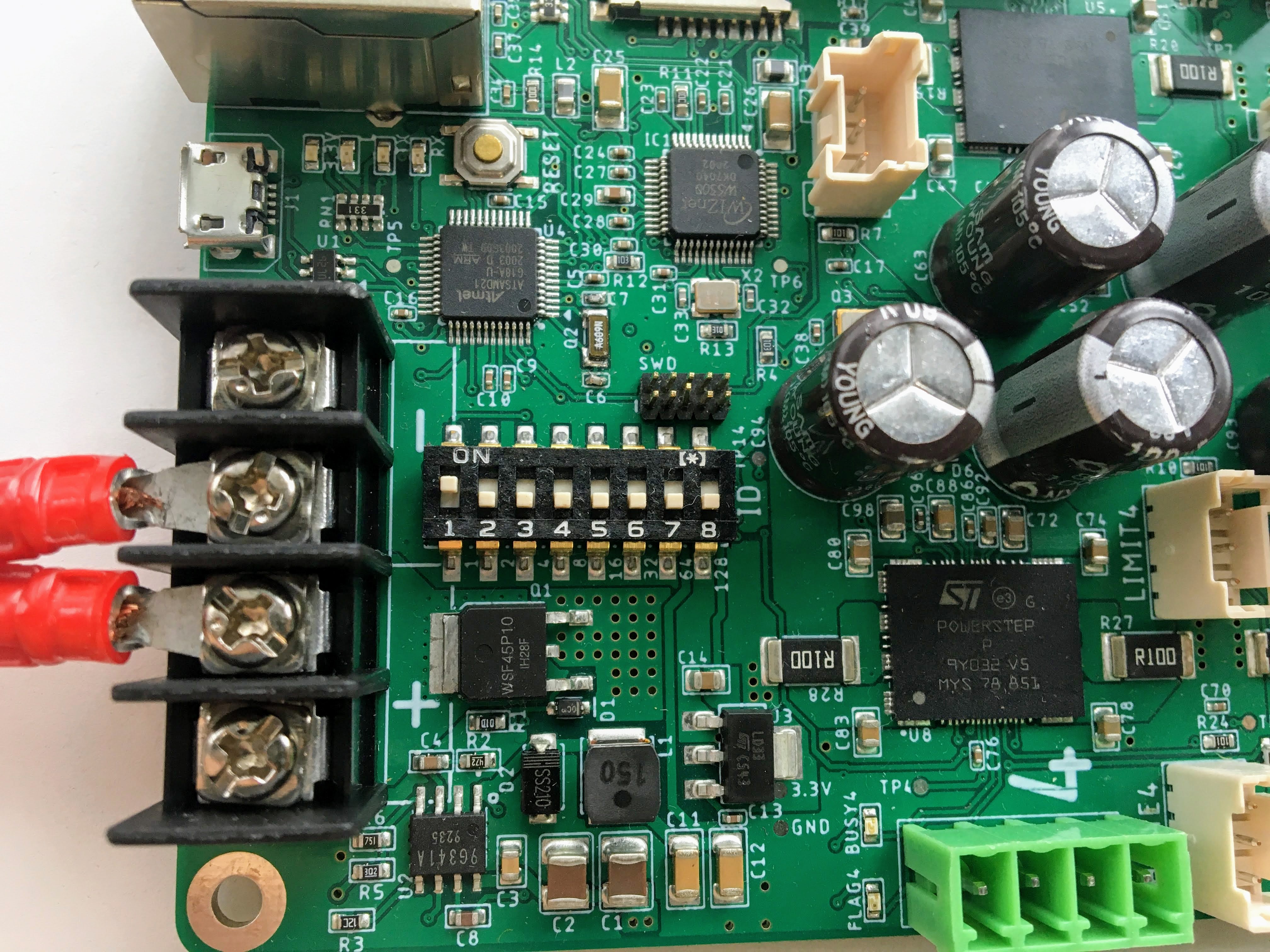
The DIP switch on the board must be set to 1. That is, only the digit 1 is ON, and all other digits are OFF. In this state, the board has the following network settings:
| item | assigned value |
|---|---|
| IP address | 10.0.0.101 |
| Reply address | 10.0.0.10 |
| OSC incoming port | 50000 |
| OSC outgoing port | 50101 |

Now you can turn on the power. On the backside of STEP400, there are several pins where the power supply voltage is applied, so either attach spacers to the holes on the board or place the board on a non-conductive material.
Set the static IP to the Ethernet port that STEP400 is connected to. Set it as follows:
| Item | Assign value |
|---|---|
| IP address | 10.0.0.10 |
| Subnet mask | 255.255.255.0 |
Usually you can leave the rest of the items empty, like Gateway or DNS. How to set up a static IP depends on the operating system.
Provided that you don’t encounter problems with these settings, you should be able to check the connection with commands such as ping 10.0.0.101 from a Terminal on a Mac, or Command Prompt on a Windows computer.
From here on, the actual operations will vary depending on the environment used for control, but we will focus on describing the actual Open Sound Control messages that are sent and received.
At first, the command /setDestIp has to be sent to STEP400 to tell where response messages have to be sent. The destination address is 10.0.0.10, and the sending port is 50000. Until this command is received, STEP400 will not send any OSC messages. This is because the operation may become unstable if STEP400 continues to send OSC messages to a non-existent destination.
If /setDestIp is received without problems, you should get the following response (the receiving port is 50101):
/destIp (int)destIp[0] (int)destIp[1] (int)destIp[2] (int)destIp[3] (bool)isNewDestIp
-
destIp[0-3]: Each bytes of destIp -
isNewDestIp: Indicates whether or not destIp has been changed. 1 if it has been changed, or 0 if the same address has already been set.
Now we're ready to exchange messages.
Let's send a command to run the motor. /run (int)motorID (float)speed command causes the motor to rotate at the specified speed.
motorID specifies which motor to run (the number is printed on the STEP400 board). If you set the ID to 255, you can send the command to all motors. Possible ID values are 1, 2, 3, 4, and 255.
speed specifies the speed and the direction of the motor. The range you can specify goes from -15625.0 to 15625.0 step/s. If you're using a motor with 200 steps per revolution, you can specify 200.0 to make one revolution per second. If you specify a negative value, it will simply go backwards. For example, to make one revolution in one second for a motor connected to connector number 1, the OSC message would look like this:
/run 1 200.
Does it work? If something is wrong with the motor and you want to stop it, set speed to 0.0, or send the message /hardHiZ 255 to stop all motors.
In many cases, the motor might not be running smoothly at this point and we will need to make further setup adjustments.
In most cases, the reason for lacking motion smoothness is insufficient (or sometimes excessive) drive voltage. This can be adjusted with the KVAL register. The KVAL register specifies the voltage to drive the motor on a scale of 0 to 255, where 0 means 0V (cannot turn) and 255 means that the motor drive voltage is almost the same as the power supply voltage. For example, if you are using a 24V power supply and you specify 128 for KVAL, the motor will be driven at about 12V.
There are four types of KVAL:
| KVAL name | function | initial value at STEP400 |
|---|---|---|
| KVAL_HOLD | Holding KVAL | 0 |
| KVAL_RUN | Constant speed KVAL | 16 |
| KVAL_ACC | Acceleration KVAL | 16 |
| KVAL_DEC | Deceleration KVAL | 16 |
Let's adjust KVAL_RUN while rotating the motor at a constant speed. Send this message to rotate the motor:
/run 1 200.
You can set KVALs with this command:
/setKval (int)motorID (int)holdKVAL (int)runKVAL (int)accKVAL (int)setDecKVAL
Where motorID is 1-4, 255. Possible value for each KVAL range from 0 to 255.
Let's set KVAL to 0 for stopping, and gradually increase the value for acceleration and deceleration to the same value as KVAL for constant speed.
/setKval 1 0 24 24 24
This message specifies the first motor KVAL as 0 for holding, and the rest of it as 24 (approximately 9% of the power supply voltage).
Gradually increase the numbers as follows, and somewhere along the line the motor will begin to turn quietly.
/setKval 1 0 32 32 32
As you increase KVAL, the torque will increase as well, but the motor will generate more heat and the vibration will also increase, so make sure to make appropriate adjustments to suit the load.
- home
- Tutorial
-
Connections and settings
- Power supply and Motor
- Sensor and Switch
- Network and DIP switch
- Setup with a microSD card
- Example parameter values for example steppers
- Function description
- OSC command reference
- Technical information

