-
Notifications
You must be signed in to change notification settings - Fork 1
5. Combine segments together into a single arm
Oliver Fischer edited this page Mar 18, 2022
·
1 revision


| small | medium | large |
|---|---|---|
| ?? g | ?? g | ?? g |
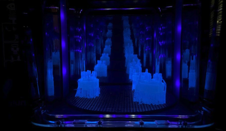
- Print the internal structure using the Form 3 printer.
- STL files are saved as connector_AtoB.STL (where A & B are segment IDs)
- Load STL models to PreForm, and slightly tilt them (as should be for most Form 3 prints). Rigid resin should be used for printing (barbed connectors may not be rigid enough if printed with elastic / flexible resin)
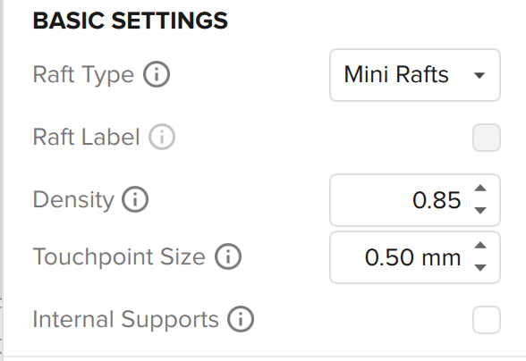
- Deselect "Internal Supports" so that internal tubes are not blocked with supports. Optionally, use "Mini Rafts" and set slightly reduced touchpoint density (for easier raft removal).
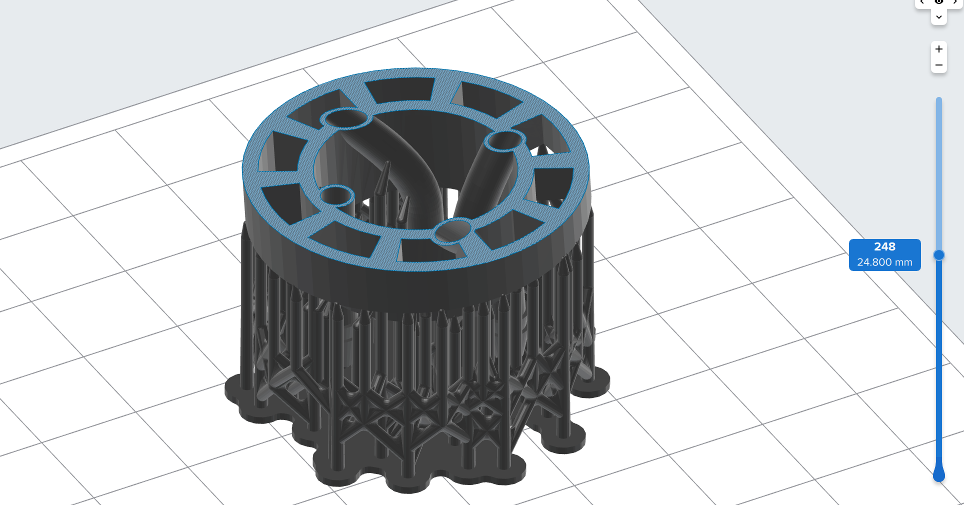
- after adding supports, double-check to see that the internal tubes are empty, with the sliced view.
- Print!
- Post-process the printed connector piece
- Remove from the Form 3 stage, and wash with IPA using Form Wash.
-
BEFORE curing, expose both sides of the barbed connector (cut through support material with nippers), and pass a thick string (e.g. cable) through the internal tubes. Take it out of the other side to ensure that no resin residue remains inside (it is impossible take blocked resin out after curing).
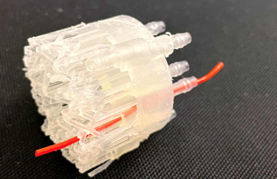

- Cure the printed part, and remove any remaining support material.
- Spray mold release to the mold (don't spray the Form 3 structure, as silicone will be cast around it). Assemble the mold for casting.
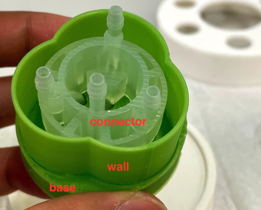 Make sure the connector and base sit flush with each other.
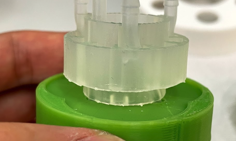
- Cast silicone to create a single connector piece. Silicone should be poured to the brim. Use the stiffer Dragon Skin 30 for this part, to constrain deformations at the end of each segment. Take care not to pour silicone into the tubes (even if this happens, they can be removed by passing through the thick string again, after curing)
- Recommended way to remove from mold:
- first remove the bits of silicone from the bottom hole
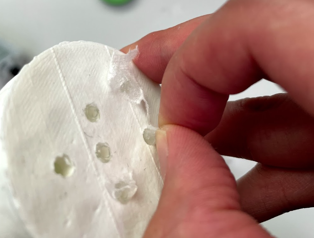
- separate silicone from wall, e.g. with flathead screwdriver
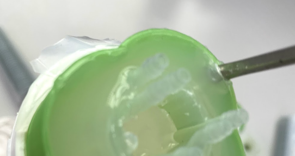
- separate silicone from base. Insert screwdriver being careful not to pass it through areas with the barbed connectors.
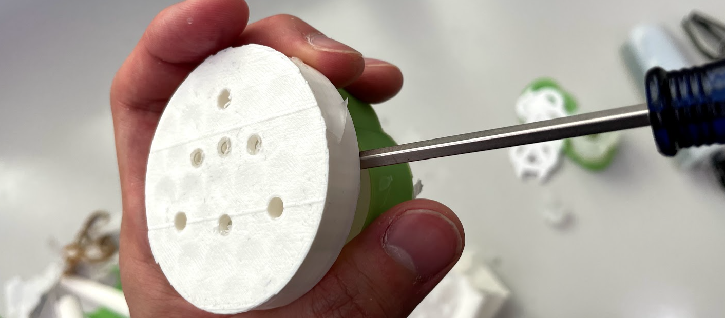
- first remove the bits of silicone from the bottom hole
- If some silicone leaked during the curing process and the top surface is concave, you may have to do a second casting to make the silicone become fully level with the internal connector (it would be even better if this could be prevented with the design...).
- Remove excess bits of silicone (e.g. attached around the barbed connectors)
- Are internal tubes not blocked / leaking? Test by passing air with syringe.
- Are barbed connectors intact? (some fractures near the tip is fine)
- if there is a hole in the Form 3 print, it may be patchable with shrink wrap.

- First, glue the connectors to the base side of each segment (side with larger diameter). (because it's easier to do it in separate steps than glue everything together in one go / the side of the connector and segment with electrical connectors must be exposed for the next step)
Clean the surfaces you want to attach with IPA, and apply glue (Silpoxy or Dragonskin 10) to both sides and glue together.
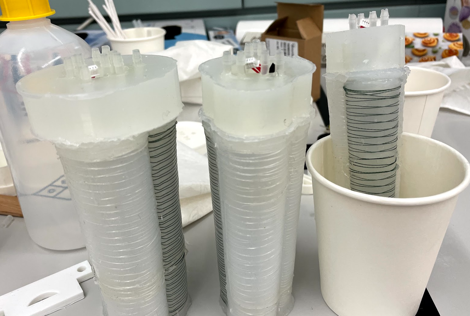
- After curing, test the airtightness with syringe.
- Assemble each segment. It is recommended to assemble in stages, i.e. glue one pair, let it cure, test electrical & pneumatic connection, glue one part, and so on.
- Actuate each pneumatic line with a syringe. Make sure it moves a chamber, or air comes out of the passthrough air tunnel at the tip of the segment. Does it not leak even at higher pressures?
- Check that the sensors can be read from with an Arduino.