-
Notifications
You must be signed in to change notification settings - Fork 0
Small_Bore_Imager_Mechanical

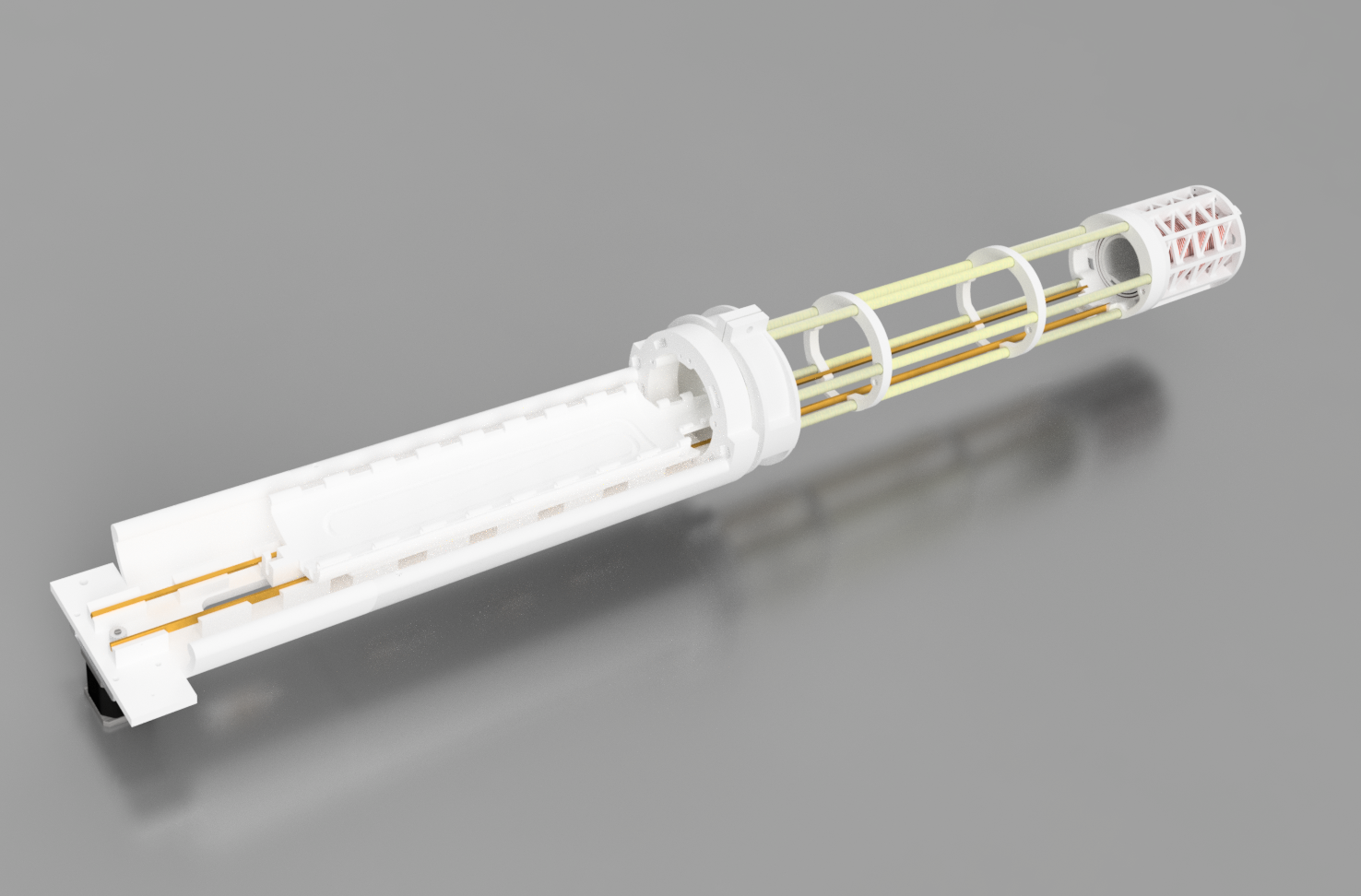
The mechanical design as a whole is relatively complex with on the order of 100 uniquely designed component, yet each sub-system is fairly straightforward with a few notable exceptions. Firstly, the rotary union requires some finesse to implement properly, and the same goes for the translational motion of the bed/sample holder, but both of these parts are hopefully are described sufficiently in their respective pages. With that said, this page should give an overview on the assembly and each major sub-assembly.
Given the number of unique parts, we have created a spreadsheet which we hope will aide in the project management and budgeting. Besides the template being a useful organization tool, the part numbering system is very important with respect to clearly discussing the system.

The “rotating gantry” encompasses all of the rotating components of the system as well as the slip ring/rotary union. For the most part, the system is constructed of fiberglass sheets (FR4) with 3D printed elements to help support it and a large timing belt pulley which serves as the method for turning it. The structure supports the FFL magnets, the shift coils, and the water cooling. The primary mechanical loads within the gantry are due to the weight forces, magnetic repulsion, and the torque required to overcome the friction inherent in the rotary union. Of these, the rotary union’s required torque plays the greatest role in the design because it requires substantial energy from the motor to overcome. Regarding material selection throughout, polymer-based materials are preferred because metallic components will generate large eddy currents from the shift coils, and although these eddy currents don’t make the system dysfunctional, it will cause an increased phase-shift in the shift field (with respect to applied voltage) and diminish the efficiency. To overcome this, when we used metallic components such as in heat sinks, we added a dielectric break.
 The stationary frame is constructed from extruded aluminum framing and besides supporting the gantry and the stationary tube, the frame should play a role in vibration management. Vibrations can be rather insidious as they will manifest as noise in the signal. To handle these vibrations we are using a heavy wooden bench top and use vibration dampening padding between the motor housing and the frame.
 The internal coils consist of the Tx/Drive coil and the Rx coils/gradiometer which are epoxied together. The coil assembly is then set so the gradiometer coil nearest to the forward end of the coil (where the rodent/sample would enter) is located at isocenter. They are held in place by a series of wedges that engage via threaded rods. The other key component within the copper tube is the bed/rail assembly. The rails enable consistent, stable travel down the bore. The travel is driven by a stepper motor which is coupled to the bed through a timing belt. The “bed” can either be a platform designed for an anesthetized rat, or SPION filled phantoms.
