-
Notifications
You must be signed in to change notification settings - Fork 0
MPI_Rotary_Union
Overview CAD Files

With an FFL-based scanner, the imaging time is defined by the time it takes to acquire 180 degrees of projections. In a mechanically rotated FFL, that means it is defined by the speed at which the FFL magnets are spun. With the shift coils necessitating both electrical power and water cooling to be delivered to the gantry, as the designer we are left with two options: you may either loosely wrap the water/power cables to there is enough slack to turn 180 degrees and then change directions and image the other way. This has the notable benefit of simplicity and cost-effectiveness, but the downside of this approach is a potential systematic error by not fully rotating, the limitation of temporal resolution, and mechanical stresses of rapid starts and stops. The other option is to use a slip ring/rotary union to deliver the power and water respectively. This page will describe the rotary union and the slip ring is a commercial product listed
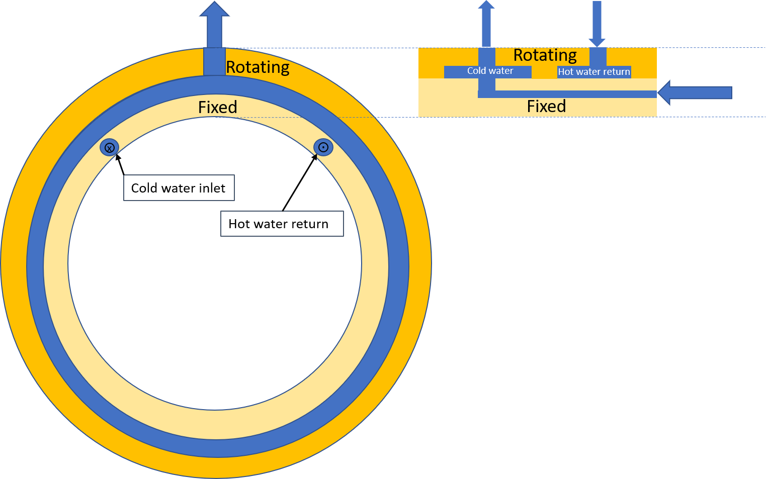
The principle for rotary union operation is that there are two primary components: there is a stationary inner piece and a rotating outer shell. Between these parts there is a circumferential groove that is filled with water from a inflow pipe on the stationary part. On the outer shell there is a radial hole that is aligned with the interior water-filled groove, therefore irrespective of angular position, the outer hole is connected to the water groove. There are two of these groove/hole combinations-- one for inflow, the other for outflow. Below is an illustration I made hopefully clearing up the functional idea. The premise is straightforward, but the design gets tricky because nearly every interface needs to be dynamically sealed without causing too much friction. Our design isn't perfect and if you intend to make it I would implore you to reach out to us and discuss a few potential improvements that have not been drawn yet.
