-
Notifications
You must be signed in to change notification settings - Fork 0
Home
| Gantry photograph | Gantry rendering |
|---|---|
 |
 |
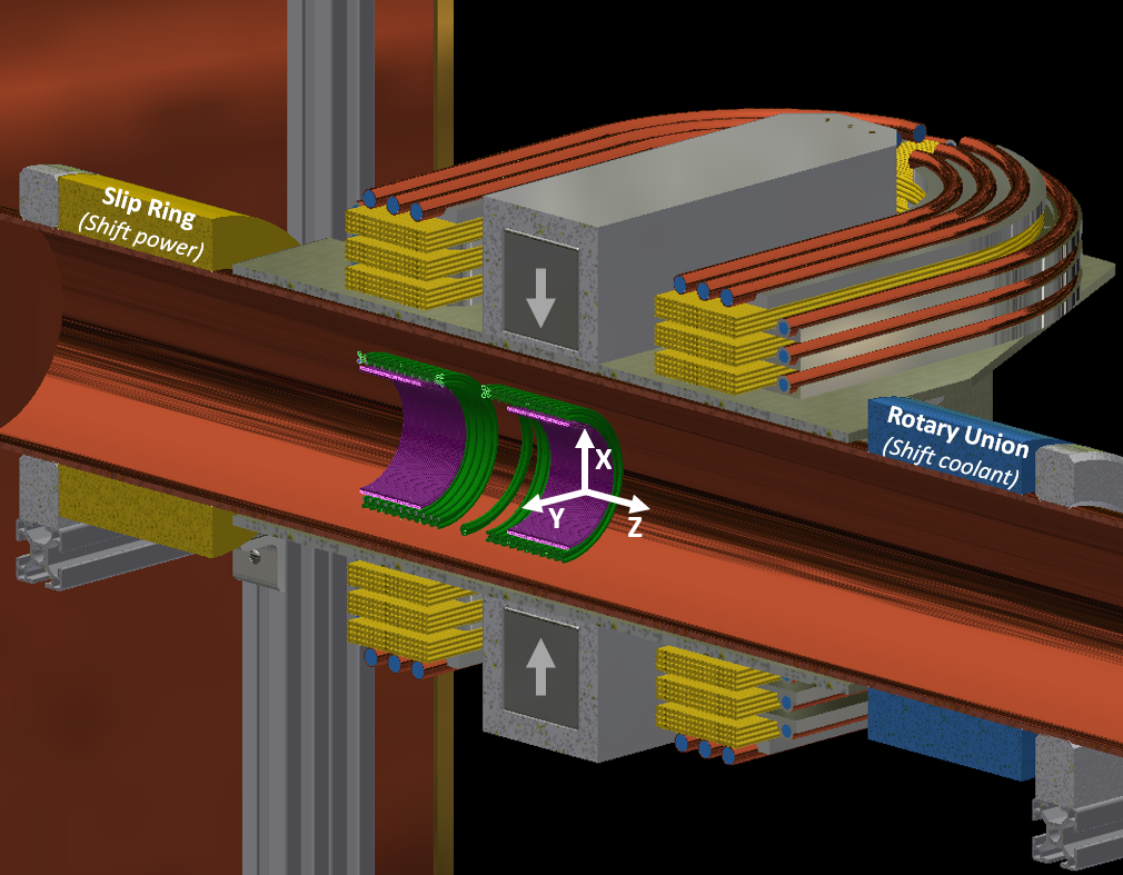
Figure 1: Left) A photograph of the MPI system. The amplifier racks containing the drive amplifier and shift amplifiers are out of view. Right) A cross-sectional rendering of the MPI system. In this rendering, the receive (“Rx”) coils are in purple, drive coils are in green, and shift coils and the slip ring are in yellow. The rotary union and water within the cooling tubes are in blue
The goal for the imager is to image the rat brain undergoing functional changes. This implies a few design criteria: First, the imager should image sufficiently fast to resolve changes in the brain (~5-20 sec.). Second, stability is essential to the application because the goal is to resolve time-series changes in the brain. The experiments are expected to last ~30 min, so the device should be stable over that time. If the instrumentation drifts excessively, this will corrupt the interpretation of the data. Finally, spatial resolution should be ~2-3mm to ensure the anatomy can be differentiated.
The imager employs the FFL-based MPI imaging scheme as FFL-MPI has higher sensitivity when compared to FFP MPI due to receiving the signal from a greater region at any given instant (1). We transmit through a solenoidal drive coil through a stability-optimized filter. We receive through a solenoidal pair gradiometer coil. The received signal is fed through a band-stop filter to notch out the fundamental feedthrough and into a JFET pre-amp.
Due to using permanent magnets to generate the FFL, we must use a physically rotating gantry to enable taking projections around the bore. Further, as we are largely interested in looking at functional activity with temporal changes every ~5 seconds, we chose to have this gantry be continuously rotating as opposed to stopping and reversing after each image. Facilitating rotation, there is an electrical slip ring to transmit electrical power to the shift coils and a water rotary union to transmit coolant to the shift coils. The other main mechanical consideration is the sample bed. The bed is controlled via a long fiberglass threaded rod directly coupled to a stepper motor.
Gradient: 2.83 T/m
Drive field: 8 mT
FOV: ~30 mm diameter
Resolution: ~3 mm (Synomag-D, In-plane)
Temporal Resolution: Under 3 seconds
Sensitivity: 6.7 ng in 5 seconds
We employ an array of four N48 NdFeB permanent magnets to form each one of the two opposing FFL magnets. The dimension of each array is 2” x 2” x 16” consisting of four 2” x 2” x 4” blocks that have been glued together and are contained within an ABS enclosure. The magnets are located ~5" apart (when measured between their inner faces), this separation distance inherently determines the gradient strength, shift coil requirements, bore diameter, etc.
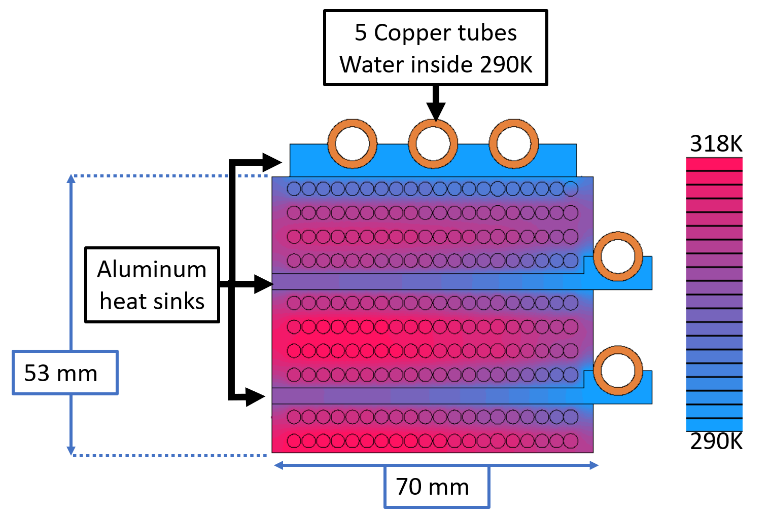
We have chosen to use “racetrack” shaped shift coils assembled in four-layer sub-assemblies separated by heat sinks. Each layer is composed of 20 turns of 10-gauge solid magnet wire. The geometry was determined by the requirement to make the coils go around the FFL gradient magnet, and designing for a non-square cross-section because flatter geometries enable more efficient heat removal due to greater surface area. Current in the coils was determined by knowing the FFL must be shifted the entire FOV (up to 15 mm each way). With a gradient of 2.83T/m and a field efficiency of ~1mT/A, to shift 15mm you need 42.5 Amps (peak).


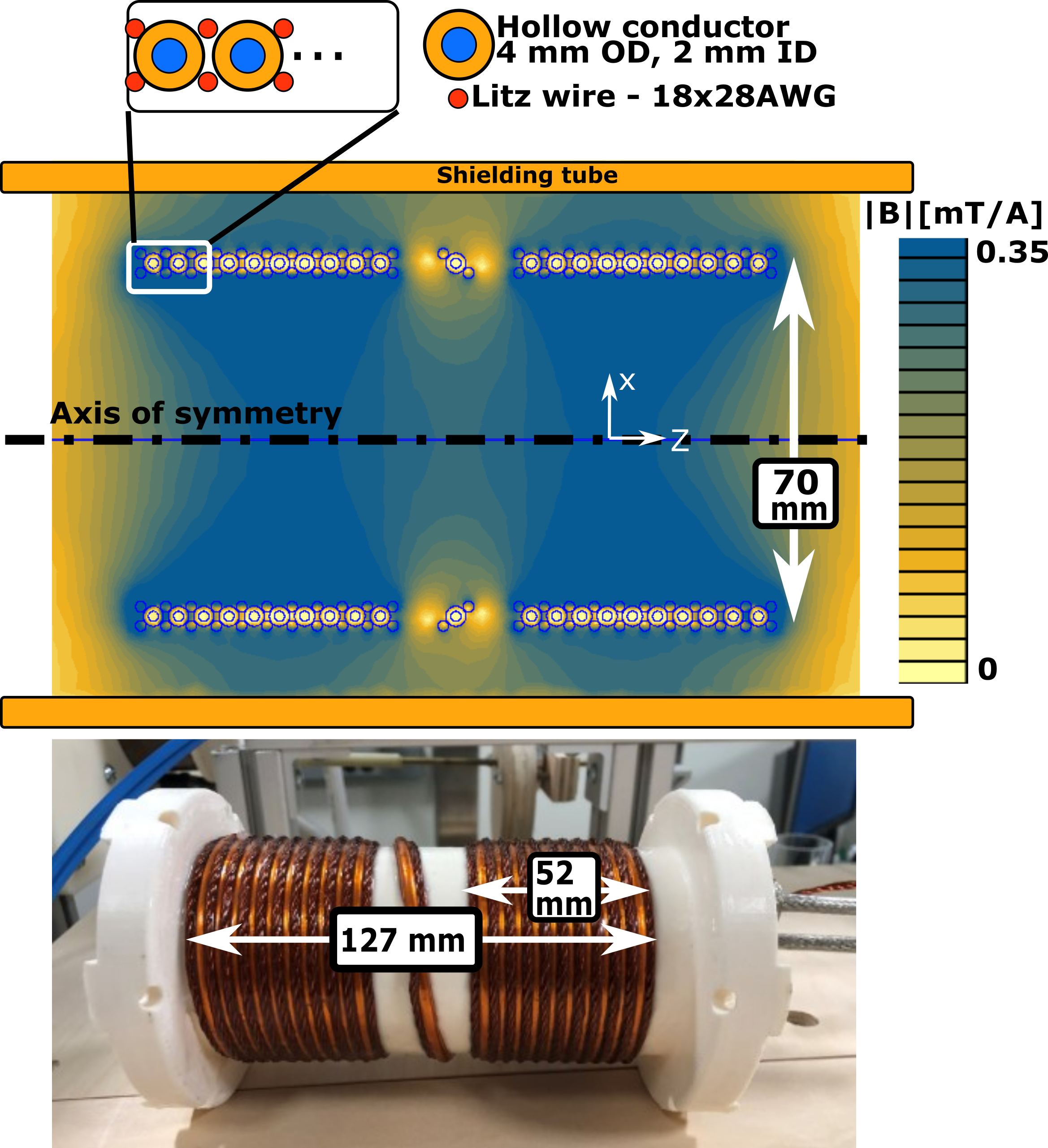
The drive coil is a three-layer design consisting of both Litz wires and water-cooled hollow-conductors. They were designed to achieve 8 mT within the imaging volume while maintaining ~10 oC above water coolant at steady-state. The wiring configuration was picked to incorporate the benefits of both Litz wire and water-cooled hollow conductors. Litz wire is significantly more efficient than copper tubing (skin/proximity effect is mitigated in Litz), but has no intrinsic heat-removal capacity. The water-cooled tubing has relatively much lower efficiency, but this is made up for by the fact it has excellent thermal contact with the water, and acts as a heat-sink for the Litz wires. Because the tubing is larger (4 mm diameter) the smaller Litz (~2 mm diameter), can sit within the grooves formed by the tubing.
The drive filter is an essential (often overlooked) component in MPI with two primary roles. First, as the name implies, it filters the high-power waveform from the amplifier ensuring the drive coil is powered by a highly pure (better than -100 dBc THD) and stable (~1%/30 min) sinusoid. The second role is to ensure the amplifier can supply said power, and further make sure the amplifier is "seeing" an impedance which it is designed for.
At the same time, it is beneficial to keep the losses within the filter at a minimum. This both helps with stability as well makes the thermal design simpler. An inefficient system will drift and/or require significant effort to cool it down. Excessive losses also will diminish the amplifier's performance.
The Rx coil is designed as a pair of oppositely wound coils ("gradiometer") to minimize the amount of drive field "feedthrough". This coil is wound from Litz wire to reduce the thermal noise generated from the coil.
The Rx filter is also central to MPI, and its structure substantially impacts the received signal and reconstruction. We choose to use a notch filter (blocking the drive frequency, f0) and pass only 2f0 and higher. Yet this is not necessarily the “correct” approach as it has been shown to be possible to attenuate feed-through via passive and active means and use the true signal at the drive frequency to boost the SNR as D. Pantke et al. suggest in their recent paper(2). Though for simplicity, this has not been implemented.
For the data presented here, we utilized an amplifier from University Medical Center Hamburg Eppendorf, which utilizes a JFET front-end similar to the one presented here (3).See the OS-MPI page on pre-amplifiers for alternative open-source preamplifiers.
Part No. 1000 in CAD
The “rotating gantry” encompasses all of the rotating components of the system as well as the slip ring/rotary union. For the most part, the system is constructed of fiberglass sheets (FR4) with 3D printed elements to help support it and a large timing belt pulley which serves as the method for turning it. The structure supports the FFL magnets, the shift coils, and the water cooling with the primary mechanical loading being due to the weight forces, magnetic repulsion, and the torque required to overcome the friction inherent in the rotary union, where the rotary union’s torque, being dynamic friction, requires substantial energy from the motor to overcome. Regarding material selection throughout, polymer-based materials are preferred because conductive components will generate large eddy currents from the shift coils, and although these eddy currents don’t make the system dysfunctional, it will cause an increased phase-shift in the shift field (with respect to applied voltage) and diminish the efficiency. To overcome this, when we used metallic components such as in heat sinks, we added a dielectric break if possible.
Part No. 2000 in CAD
The stationary frame is constructed from extruded aluminum framing and besides supporting the gantry and the stationary tube should play a role in vibration management.
Part No. 3000 in CAD
The internal coils consist of the Tx/Drive coil and the Rx coils/gradiometer which are epoxied together. The coil assembly is then set so the gradiometer coil nearest to the forward end of the coil (where the rodent/sample would enter) is located at isocenter. They are held in place by a series of wedges that engage via threaded rods. The other key component within the copper tube is the bed/rail assembly. The rails enable consistent, stable travel down the bore. The travel is driven by a stepper motor which is coupled to the bed through a timing belt. The “bed” can either be a platform designed for an anesthetized rat, or SPION filled phantoms.
 (1) Weizenecker et al., Magnetic particle imaging using a field free line, 2008
 (2) D. Pantke et al., Multifrequency magnetic particle imaging enabled by a combined passive and active drive field feed-through compensation approach, 2019
 (3) Graeser et al., Towards Picogram Detection of Superparamagnetic Iron-Oxide Particles Using a Gradiometric Receive Coil, 2017