-
Notifications
You must be signed in to change notification settings - Fork 5
Extended push to talk output
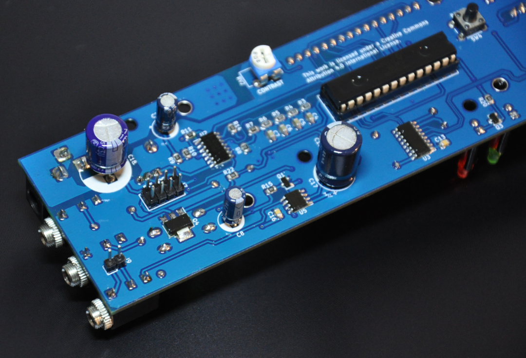
Extended push-to-talk output can use to get multiple PTT interfacing options from the auto keyer. This header is located at the bottom of the PCB and designated as J7.

This section of the documentation describes a few common interfacing options possible with this terminal.
- +12V : DC output terminal. The output voltage of this pin is related to supply voltage.
- +5V : Regulated +5V DC output. With the provided PCB layout, the maximum allowed load for this pin is less than 200mA.
- PTT-OC-OUT : Open collector output terminal. This pin is directly compatible with a wide range of PTT interfaces. This terminal is also accessible through J6 jack socket.
- PTT-OUT : PTT control output from the PIC16F886 MCU. This terminal is provided to interface with external PTT control logic circuits and it provides 5V logic level output.
- GND : Ground.
This interface circuit is suitable for control of high voltage systems. Also, this method provides complete isolation between the transmitting apparatus and auto keyer.
For K1, use high profile 12V relay.
This option is suitable to drive electronically controlled PTT circuits. Compare with the relay-based approach this method provides much more reliable, noise-free output and also ensure strong isolation between each system.
Due low power requirement this interface can drive using +5V terminal. The value of R1 is depended with specifications of the optoisolator (U1).
The main objective of this interface option is to provide TTL compatible 5V logic output to drive an external logic circuit(s). This output can directly use with compatible systems such as with Arduino.
This terminal is not designed to drive high current loads. To archive maximum reliability it's recommended to couple this terminal to external circuitry through a logic buffer.


