-
Notifications
You must be signed in to change notification settings - Fork 225
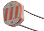
LDR SENSOR
Jaume Olivé Petrus edited this page Aug 28, 2017
·
16 revisions
| What | Comments | |
|---|---|---|
| Identifier | LDR | |
| Interface | ADC | |
| Provides | illuminance | lux (*) |
| Properties | R1 R2 |
R1 resistance in ohms (**) R2 resistance in ohms (**) |
 |
(*)
| lux | Surfaces illuminated by |
|---|---|
| 0.0001 | Moonless, overcast night sky (starlight) |
| 0.002 | Moonless clear night sky with airglow |
| 0.05–0.36 | Full moon on a clear night |
| 3.4 | Dark limit of civil twilight under a clear sky |
| 20–50 | Public areas with dark surroundings |
| 50 | Family living room lights |
| 80 | Office building hallway/toilet lighting |
| 100 | Very dark overcast day |
| 320–500 | Office lighting |
| 400 | Sunrise or sunset on a clear day |
| 1000 | Overcast day: typical TV studio lighting |
| 10,000–25,000 | Full daylight (not direct sun) |
| 32,000–100,000 | Direct sunlight |
(**)
LDR component must be part of a voltage divider circuit:
LDR can be placed in the R1 or R2 location:
- R1 location: R1 = 0, R2 = fixed resistor.
- R2 location: R1 = fixed resistor, R2 = 0.
Typically the fixed resistor is 10K = 10.000 ohms.
Sensor default values are R1 = 10.000 ohms / R2 = 0.

