Skip to content

Step 06_Assemble Adaptrboard

Marco Busse edited this page Jun 12, 2020 · 1 revision

Table of Contents

Assemble the Adaptrboard


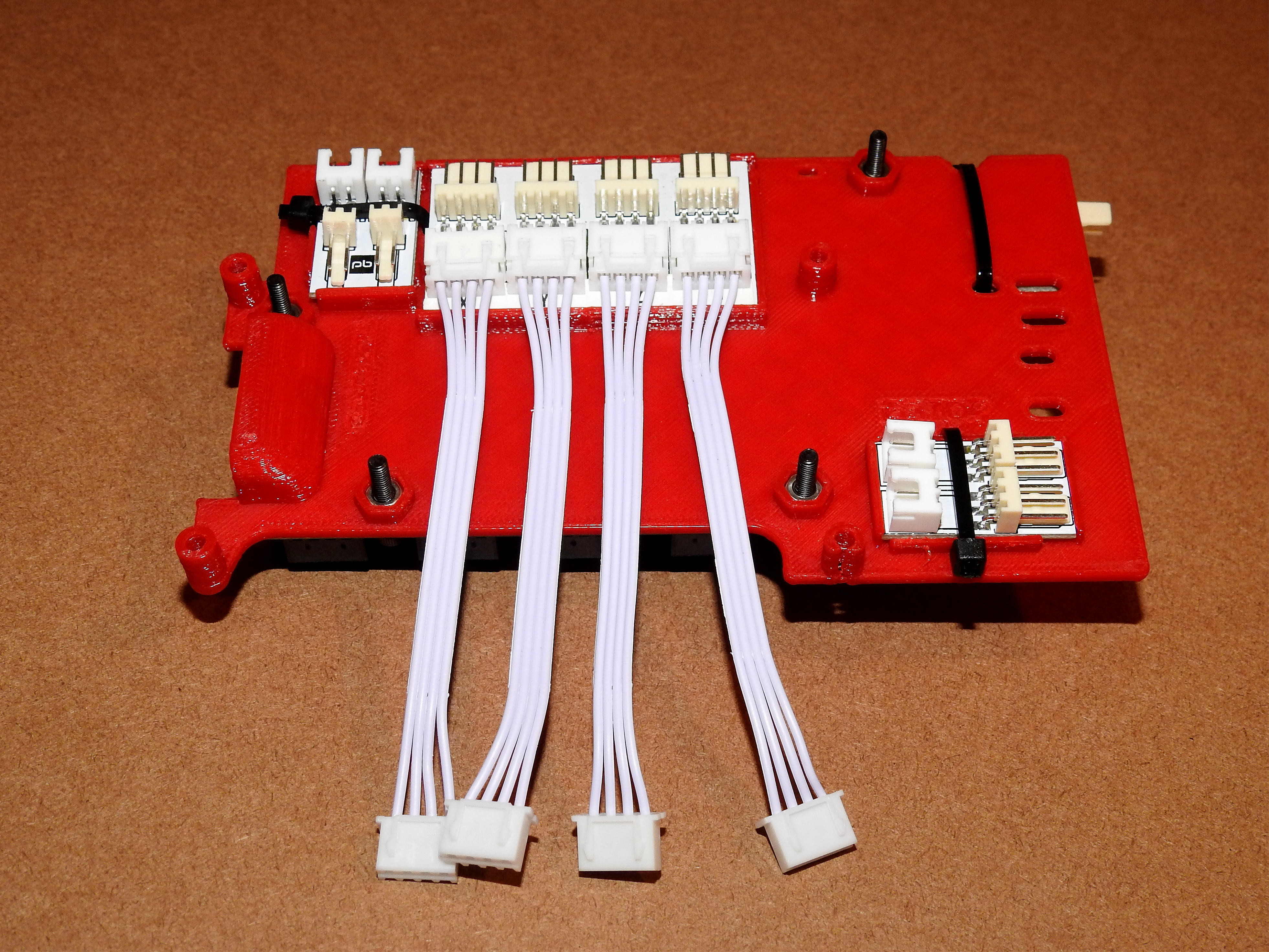
Underside

Start with the underside of the Control Board Mount piece you printed out earlier.

Attach the Stepper Motor Interface

  1. The Interface board snaps into the large rectangular section on the bottom of the Control Board Mount.
    1. The pins face outward, while the JST connectors face inward.
    2. Snapping it into place may be a little difficult. I found it easiest to:
      1. First angle the inside edge of the interface board under the inside inner lip of the holder
      2. Then place a piece of thicker paper material (such as a business card) between the outer lip and the interface board
      3. Push down on the outer edge of the interface board - it should slide along the card and into place
      4. Then pull out the paper leaving the interface board snapped into the holder

Attach the Thermistor Interface

  1. The Thermistor Interface Board snaps into the smaller rectangular section to the left of the Motor Interface Board.
    1. This time the pins face inward, while the JST connectors face outward.
    2. Snapping it into place is easier than with the Motor Interface Board.
    3. Once in place, secure it with a zip tie using the holes on either side of the board.

Attach the EndStop Interface

  1. The EndStop Interface Board snaps into the smaller rectangular section toward the bottom right of the mount board.
    1. The pins face outward, while the JST connectors face inward.
    2. Once in place, secure it with a zip tie using the holes on either side of the board.


Top Side

Now flip the mounting board over to the top side. We will be attaching the Z-Probe interface board along with the BTT SKR Mini CPU.

Attach the Inductive Z-Probe Interface

  1. In the final version of the kit, there should be an aux fan output connector on the Z-Probe interface board to the left of the Fan 1 out connector. This will be used to connect the stepper driver fan later on.
    1. On my beta kit, this was not attached, so before attaching the interface board to the Control Board mount, I soldered on a 2pin JST-XH 2.54mm connector (not included) into the empty aux fan holes to the left of the Fan connector.
    2. Make sure to pay attention to the orientation of the connector. +/- is marked on the board and the opening in the connector should be facing outwards.
    3. I used a JST-XH because that was the connector on my fan, but you might need to use a 2-Pin Micro JST 1.25 (not included) instead depending on what connector is on your 30x30mm fan.
  2. The Z-Stop Inductive Probe Interface Board snaps into the rectangular section in the bottom right of the mount board.
    1. There is a hole in the center of the interface board that aligns with a hole in the Control Board mount that you can use to make sure you are lined up correctly. But truthfully, it doesn't have to be exact.
    2. This time the pins face out and the JST connector (opposite of the pins) faces in.
    3. Secure in place using a tie wrap, but keep it a little loose for the moment and don't cut the end off of the tie wrap yet. You want to be able to slip some wires under it on the other side of the board later on before final tightening.

Attach the BTT SKR Mini E3 32Bit Control Board

  1. If you are using the "M3 Nut" version of the Control Board Mount, flip the mounting board back over and push 4 M3 hex nuts (not included in the kit) into their appropriate openings. If you are using the plastite screw version, you can skip this step.


  2. Back on the front side of the mount board, align the BTT such that 4 of its mounting holes align with the holes in the mounting board.
  3. Secure in place using 4 plastite screws (or in the case of the "M3 Nut" version, 4 3x15mm bolts (not included in the kit).
    1. Tighten them firmly, but making sure to put even tension on all four so as not to bend the board.

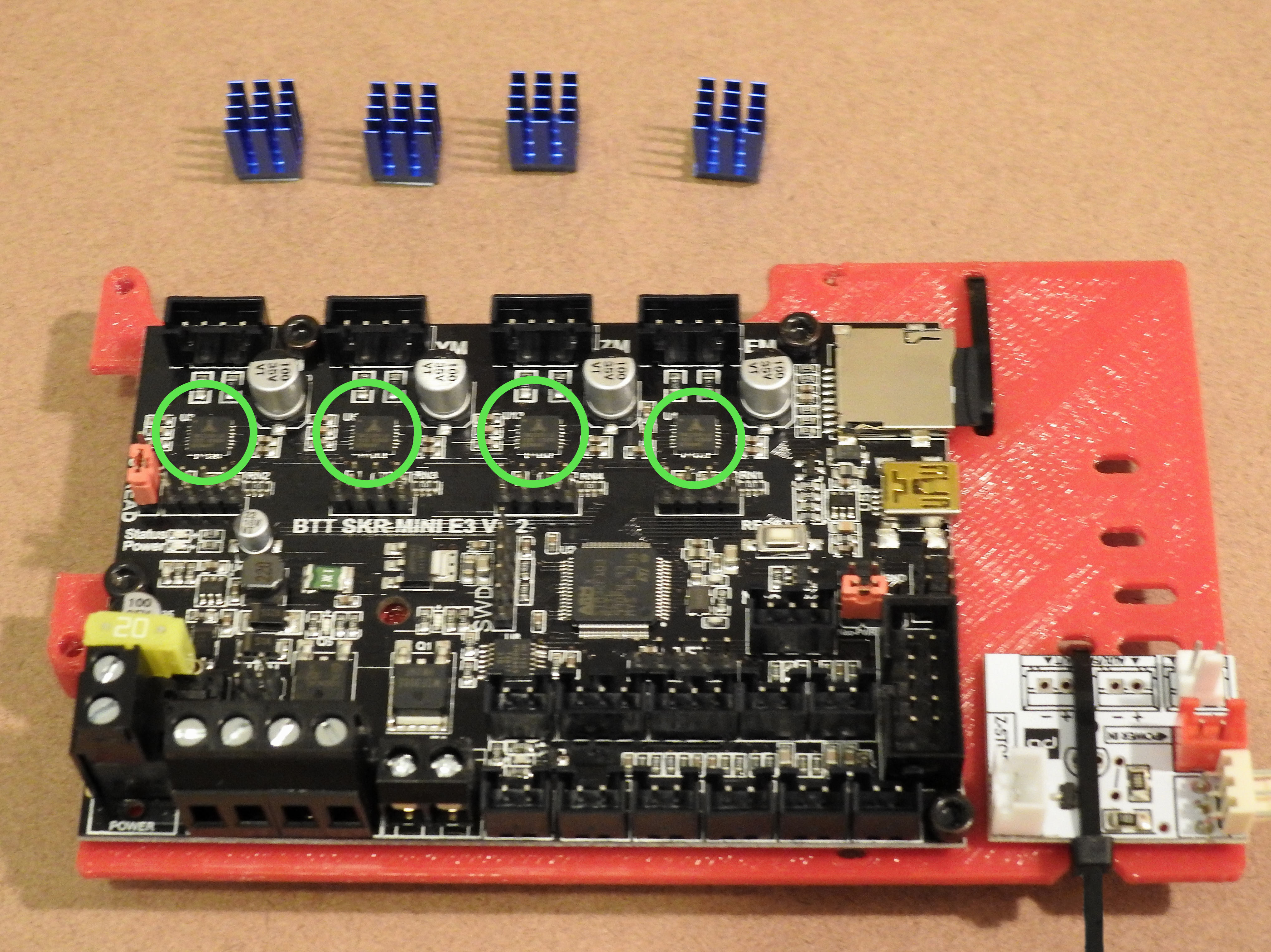
Attach the Stepper Driver Heatsinks

  1. Attach the 4 heat sinks to the BTT Mini E3 stepper drivers
    1. Align the fins to that they are horizontal
    2. Peel the backing off of the bottom
    3. Press firmly into place, making sure to center on the little square chip


Attach the MOSFET Heatsink (Optional)

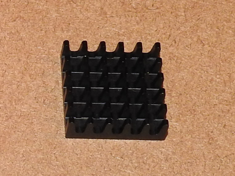
I am not sure if this will be included in the final kit, but it is a good idea to put a heat sink on the heated bed MOSFET. The heat sink I was provided with in my Beta kit was big enough to cover both the hot bed and the power MOSFETs, and then some. It also had a metalized adhesive that I was worried could potentially cause a short if the heatsink were to tip off the MOSFETs and onto the board. If you are providing your own, a heatsink approximately AAxBB would still cover both MOSFETs and be less likely to tip. Assuming you do have a large one, one idea is to only expose the part of the adhesive that will be touching the MOSFETs, and keep the other area covered (and non-conductive).
  1. Use an exacto knife to score the adhesive backing cover in the area where the two MOSFETs will be pressing against the heat sink.
  2. Peel away just this area of the backing
    1. This prevents the rest of the conductive metal adhesive from being exposed
    2. This is a precaution since the heatsink is so large - we don't want it to short out anything should one end fall down onto the board.
  3. Gently press the heatsink onto the MOSFETs


Wire the Interface Boards to the SKR

  1. Connect the Z-Probe Interface Board to the SKR
    1. Using a 2-pin cable, connect the Z-Stop Interface Board's power input (red connector) with FAN 1 on the SKR board.
    2. Using a 2-pin cable, connect the Z-Stop Interface Board's Z-Stop port to the SKR's Z-Stop connector
  2. Connect the Stepper Driver Interface Board to the SKR
    1. Connect the four 4-pin cables to the JST-XH connectors on the Stepper Interface Board
    2. Flip the mount board over, and connect the other end of the cables to the XM,YM,ZM, and EM ports on the SKR.
  3. Connect the Thermistor Interface Board to the SKR
    1. Place the mount board so that the Thermistor Interface Board is at the top left:
      1. Using a 2-pin cable, connect the outer JST-XH connector on the interface board to the THB (Thermistor - Hot Bed) port on the SKR
      2. Using a 2-pin cable, connect the inner JST-XH connector on the interface board to the TH0 (Thermistor - Extruder 0) port on the SKR
    2. Note - that it is possible that on the underside of the interface board, the Hot End and Bed connectors may be labeled in reverse. Whatever the case, hook things up as described above. This keeps things nice and clean and avoids cable wires crossing over each other. The important things is that the hot bed and hot end thermistors are connected to the interface board in the same order that the cables connect from it to the SKR.
  4. Connect the X/Y endstops on the interface board to the X Stop / Y Stop ports on the SKR
    1. The top plug on the interface board goes to the X Stop port on the SKR (left), the bottom goes to the Y Stop connector (to the right of the X stop).
    2. Note - In my beta kit, the wires were not long enough to reach and I had to splice in some extra wire to correct this. This is why the connection to the SKR has red/black wires at the connector. I am told in the final kit the wire length will be increased from 100mm to 150mm, so this should not be an issue at that point.Also please note that the first picture to the right makes it look like the X-Stop connector at the interface board goes to the right connector (Y-Stop) on the SKR. This is not the case. The bottom (X-Stop) connector on the interface board goes to the left connector (X-Stop) on the SKR.


Attach the Stepper Driver Fan

  1. Procure a 30x30x15mm 12v fan (not included in the kit)
  2. Hold it in place on the left side of the board next to the stepper drivers (covered with the heat sinks you put on earlier).
  3. Make sure power wire reaches the connector on the Z-Probe interface board, and that the connector is of the right type to plug into the aux fan out connector.
    1. If it is not, you may need to procure the correct connector and/or replace/lengthen the wire
  4. Before you attach the fan, do a test of screwing an M3 bolt into each of the two fan holes on the mount board, as well as the two holes on the fan shroud.
    1. Its better to do this before you attach the fan because it might take a bit of pressure to get the bolt started
    2. Once it starts screwing in to the plastic, it will form its own threads, and you can back it out
  5. Use 2 of the provided 3x15mm M3 bolts to attach the fan to the mounting board
    1. The fan should be oriented so that the labeled side of the fan faces inwards toward the stepper drivers
  6. Use the other 2 3x15mm M3 bolts to attach the fan shroud to the top two holes of the fan
    1. The fan shroud should extend over the board and cover all 4 stepper drivers and their heat sinks
  7. Plug the fan power wire into the aux fan connector on the Z-Probe interface board