-
Notifications
You must be signed in to change notification settings - Fork 2
CineRat 03 Hardware build Instructions
Frame assembly: See pictures https://www.team-blacksheep.com/products/prod:cinerat_cfhw and https://droneshop.nl/ethix-cinerat-drone
- 4x M3x7mm bolts (shortened from 10)
- rubber buffers (the ones that came with ESC)
- ESC
- 4x threaded standoffs M3x5mm standing height, 6mm thread
- Mateksys Flight Controller
- 4x threaded standoffs M3x5mm standing height. 4mm thread (shortened from 6mm, then chamfered for easier threading)
- Baseplate
- 4x M3 nuts
- 3d print raspberry pi mounting bracket
- Raspberry Pi Zero 2W
- Bottomplate (can be a baseplate, topplate or any plate with some holes for the mounting, just to protect the pi)
- 4x long M3 bolts that screw the bottom plate and the pi mounting bracket onto the standoffs
 Front -->
For awareness, we will be mounting the propellers in an "inwards" configuration:

Bottom views:
 <-- Front
 <-- Front
NOTE: If possible, wire VCC of a 5V device to 4V5 instead of 5. This way the device is also powered on USB power, and not just on battery. This is a quirk of the Mateksys H7.
Top view:
 Front -->

I'm using an Aikon AK32 4-in-1 35A (the closest official documentation in here: https://www.aikon-electronics.com/index.php?id=28).
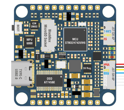
Both the Mateksys and the Aikon use tiny JST-SH-8Pin connectors to communicate. The Mateksys package or the Aikon package should include a pigtail cable and a few empty JST-SH housings that can be pinned as follows (also see images above):
| Aikon AK32 4-in-1 35A 6S | Matek H743 SLIM V3 | color | Note |
|---|---|---|---|
| - | G | black | |
| + | Vbat | red | used to power Matek, vbat sensor is on Matek |
| 1 | S1 | White | Motor 1 BDShot |
| 2 | S2 | White | Motor 2 |
| 3 | S3 | White | Motor 3 |
| 4 | S4 | White | Motor 4 |
| CR | Curr | Yellow | |
| TE | Rx8 | Blue | Low-frequency telemetry. Not configured in software. If you need RX8 for other purposes, do not connect this. |
#todo setup in BF, with Current/Voltage scale

I'm using the FrSky R-XSR EU LBT ACCESS for most of my builds. You need to update the firmware though, so they work with the EU EdgeTX/OpenTX RCs. You can ask Erik about that, I've never done it myself.
The R-XSR uses a 5-pin Molex Picoblade. They normally ship with a pigtail cable that can just be soldered onto the FC, but these cables can also be assembled from pre-crimpled wires and connector housings at the MAVLAB.
Pinout:
| R-XSR | Matek H743 SLIM V3 |
|---|---|
| GND | G (Ground) |
| +5V | 4V5 |
| S.Port | Tx7 |
| SBUS_OUT | Rx6 |
| SBUS_IN | NC (Not Connected) |
The RPi has 3 interfaces to the flight controller:
- UART to forward optitrack and position setpoints to the Matek
- Optional: SWD to wirelessly flash new software and live-debug in VSCode
- Optional: USB to wirelessly configure INDIflight via USB and download logs
A ground-station laptop connects to the Raspberry Pi via Wifi.
All of the functions require 6 GPIOs and conveniently these are all in one row. So you can get away with only soldering a 12pin 90degree male header onto the PI, like so (note that this picture only shows 9pins and only the UART connection, but I recommend soldering 12 pins):

You can then either grab a 10 or 12pin Dupont connector housing and crimp AWG 28 wire or just use a solder-type female 10 pin header:
 Left: DuPont housing, Right: Female pin header. Both are in a box in the rack next to the soldering station at the MAVLab
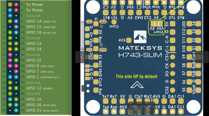
 Left: RPi pinout. Right: Matek.
| Raspberry Pi Zero 2W | Matek H743 SLIM V3 | Note |
|---|---|---|
| 5V (Pin 4) | 5V | could try 4V5 on the Matek here. I didn't test that |
| Ground (Pin 6) | G | |
| GPIO 14 (Pin 8) | RX2 | Remember that UART RX/TX should be twisted-pair! |
| GPIO 15 (Pin 10) | TX2 | Idem |
| GPIO 24 (Pin 18) | D (SWD) | Optional, for SWD debug and flash. Solder pads on Matek are on lower left edge, see above. |
| GPIO 25 (Pin 22) | C (SWD) | Idem |
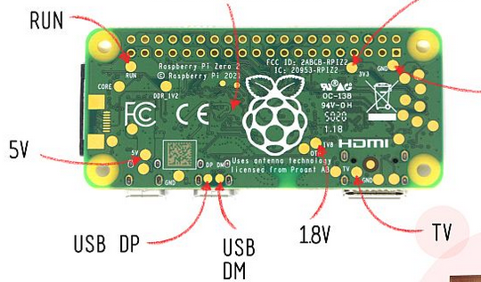
You can just use a micro-USB to USB-C cable to connect RPi to Matek. They are super bulky though, so I soldered them. Quirks:
- USB requires a shielded cable with twisted-pair wiring of D+/D-. Won't work otherwise. I just cut up a USB cable i had laying around.
- The USB interface of the Matek seems isolated somehow, so I also wired Ground and Vbus, in addition to the data D+/D-. However, Vbus may not be necessary as I may have messed up something else that made it not work before.
- NOTE: if still want to use the USB-C port of the Matek normally to connect to your PC, then you need to either power-down the Raspberry, or remove the connection. On the Raspberry Pi side of the cable, I kept the USB-micro connector for this purpose, but it's bulky...
 Backside of the PI
| Raspberry Pi Zero 2W | Matek H743 SLIM V3 | Color | Note |
|---|---|---|---|
| GND | G | Black | |
| DM | D- | White | |
| DP | D+ | Green | |
| 5V | Vbus | Red | may not be needed |
- See list of known-good cards in CineRat -- 02 Parts List and 3D prints.
- See warnings and procedures in CineRat -- 04 Software Installation and Setup#Optional -- INDIflight blackbox for logs.
I used an active beeper from Kiwi Electronics (https://www.kiwi-electronics.com/en/grove-piezo-buzzer-active-buzzer-2033), but it's not really the right one. This one would likely have been better (https://www.kiwi-electronics.com/en/piezo-buzzer-active-11258).

| Active Buzzer | Matek H743 SLIM V3 | Color |
|---|---|---|
| Q1 Emitter | Buz- | Yellow |
| J1 pin 2 | 5V | Red |
See picture below as well
| Foxeer M10Q | Matek H743 SLIM V3 | Color | Note |
|---|---|---|---|
| SPI CLK | CL1 pad | Green | Magneto. don't think it has to be twisted-pair |
| SPI Data | DA1 pad | Purple | |
| TX | RX4 | Yellow | Definitely twisted pair (top left in picture above) |
| RX | TX4 | White | |
| Ground | G | Black | |
| VCC | 4V5 | Red |
 <-- Front
NB:
- USB Vbus may not be needed and work better without
- TX/RX2 (yellow/purple) should be twisted pair
- RX6/TX7 (yellow/orange) should be twisted pair (also, no clue why I didn't chose TX6 btw)
- Some pads use horrible jumper wires that I cut and stripped. Please use proper AWG 28 wires instead.