-
Notifications
You must be signed in to change notification settings - Fork 48
SettingUpRozoFS
It is recommended to separate core traffic (application) from the SAN traffic (RozoFS/Storage) with VLANs. It is recommended to use separate ports for application and RozoFS/Client. When RozoFS and Storage are co-located, they can share the same ports. However, if there are enough available ports, it is better that each entity (RozoFS, Storage) has its own set of ports.
It is mandatory to enable Flow Control on the switch ports that handle RozoFS/Storage traffic. In addition, one must also enable Flow Control on the NICs used by RozoFS/Storage to obtain the performance benefit. On many networks, there can be an imbalance in the network traffic between the devices that send network traffic and the devices that receive the traffic. This is often the case in SAN configurations in which many hosts (initiators such as RozoFS) are communicating with storage devices. If senders transmit data simultaneously, they may exceed the throughput capacity of the receiver. When this occurs, the receiver may drop packets, forcing senders to retransmit the data after a delay. Although this will not result in any loss of data, latency will increase because of the retransmissions, and I/O performance will degrade.
It is recommended to disable spanning-tree protocol (STP) on the switch ports that connect end nodes (RozoFS clients and storage array network interfaces). If it is still decide to enable STP on those switch ports, one need to check for a STP vendor feature, such as PortFast, which allows immediate transition of the ports into forwarding state.
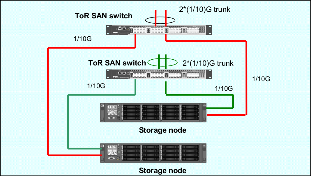
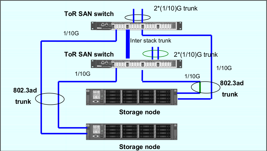
RozoFS Clients/Storages node connections to the SAN network switches are always in active-active mode. In order to leverage to Ethernet ports utilization, the balancing among the ports is under the control of the application and not under the control of a bonding driver (there is no need for bonding driver with RozoFS storage node). When operating in the default mode of RozoFs (no LACP), it is recommended that each SAN port belongs to different VLANs. Configuration with 802.3ad (LACP) trunks is supported, however the Ethernet ports usage will not be optimal since the selection of a port depends on a hash applied either an MAC or IP level.
That configuration is the recommended one for RozoFS where there is one separate Vlan per physical port. The following diagram describes how storage nodes are connected toward the ToR switches. It is assumed that the RozoFS clients reside on nodes that are connected towards the northbound of the ToR SAN switches


In that case, the ports dedicated to the SAN (RozoFS and Storage) are grouped in one or two LACP groups, depending if we want to separate the RozoFS and Storage traffic or not. They can be either reside on the same or different VLANs.

DRBD replicates data from the primary device to the secondary device in a way which ensures that both copies of the data remain identical. Think of it as a networked RAID 1. It mirrors data in real-time, so its replication occurs continuously. Applications do not need to know that in fact their data is stored on different disks.
NOTE: You must set up the DRBD devices (for store RozoFS metadata) before creating file systems on them.
To install the needed packages for DRBD see: DRBD website. The following procedure uses two servers named node1 and node2, and the cluster resource name r0. It sets up node1 as the primary node. Be sure to modify the instructions relative to your own nodes and filenames.
To set up DRBD manually, proceed as follows: The DRBD configuration
files are stored in the directory /etc/drbd.d/. There are two
configuration files which are created:
-
/etc/drbd.d/r0.rescorresponds to the configuration for resource r0; -
/etc/drbd.d/global_common.confcorresponds to the global configuration of DRBD.
Create the file /etc/drbd.d/r0.res on node1, changes the lines
according to your parameters, and save it:
resource r0 {
  protocol C;

  on node1 {
    device     /dev/drbd0;
    disk       /dev/mapper/vg01-exports;
    address    192.168.1.1:7788;
    meta-disk internal;
  }

  on node2 {
    device    /dev/drbd0;
    disk      /dev/mapper/vg01-exports;
    address   192.168.1.2:7788;
    meta-disk internal;
  }
}
Copy DRBD configuration files manually to the other node:
# scp /etc/drbd.d/* node2:/etc/drbd.d/
Initialize the metadata on both systems by entering the following command on each node:
# drbdadm -- --ignore-sanity-checks create-md r0
Attach resource r0 to the backing device :
# drbdadm attach r0
Set the synchronization parameters for the DRBD resource:
# drbdadm syncer r0
Connect the DRBD resource with its counterpart on the peer node:
# drbdadm connect r0
Start the resync process on your intended primary node (node1 in this case):
# drbdadm -- --overwrite-data-of-peer primary r0
Set node1 as primary node:
# drbdadm primary r0
Create an ext4 file system on top of your DRBD device:
# mkfs.ext4 /dev/drbd0
If the install and configuration procedures worked as expected, you are
ready to run a basic test of the DRBD functionality. Create a mount
point on node1, such as /srv/rozofs/exports:
# mkdir -p /srv/rozofs/exports
Mount the DRBD device:
# mount /dev/drbd0 /srv/rozofs/exports
Write a file:
# echo “helloworld” > /srv/rozofs/exports/test
Unmount the DRBD device:
# umount /srv/rozofs/exports
To verify that synchronization is performed:
# cat /proc/drbd
version: 8.3.11 (api:88/proto:86-96)
srcversion: 41C52C8CD882E47FB5AF767
 0: cs:Connected ro:Primary/Secondary ds:UpToDate/UpToDate C r-----
    ns:3186507 nr:0 dw:3183477 dr:516201 al:4702 bm:163 lo:0 pe:0 ua:0
    ap:0 ep:1 wo:f oos:0
The two resources are now synchronized (UpToDate). The initial synchronization is performed, it is necessary to stop the DRBD service and remove the link for the initialization script not to start the service automatically DRBD. The service is now controlled by the Pacemaker service.
Disable DRBD init script (depending on your distribution, here Debian example):
# /etc/init.d/drbd stop
# insserv -vrf drbd
Pacemaker is an open-source high availability resource management tool suitable for clusters of Linux machines. This tool can detect machine failures with a communication system based on an exchange of UDP packets and migrate services (resource) from one server to another.
The configuration of Pacemaker can be done with the crm command. It
allows you to manage different resources and propagates changes on each
server automatically. The creation of a resource is done with an entry
named primitive in the configuration file. This primitive uses a script
corresponding to the application to be protected.
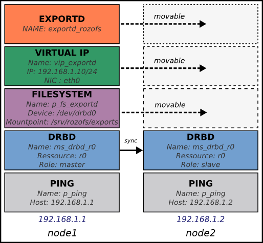
In the case of the platform, Pacemaker manages the following resources:
-
exportd daemon;
-
The virtual IP address for the exportd service;
-
Mounting the file system used to store meta-data;
-
DRBD resources (r0), roles (master or slave);
-
Server connectivity.
The following diagram describes the different resources configured and controlled via Pacemaker. In this case, two servers are configured and node1 is the master server.

The first component to configure is Corosync. It manages the
infrastructure of the cluster, i.e. the status of nodes and their
operation. For this, we must generate an authentication key that is
shared by all the machines in the cluster. The corosync-keygen utility
can be use to generate this key and then copy it to the other nodes.
Create key on node1:
# corosync-keygen
Copy the key manually to the other node:
# scp /etc/corosync/authkey root@node2:/etc/corosync/authkey
Besides copying the key, you also have to modify the corosync
configuration file which stored in /etc/corosync/corosync.conf.
Edit your corosync.conf with the following:
interface {
   # The following values need to be set based on your environment
   ringnumber: 1
   bindnetaddr:192.168.1.0
   mcastaddr: 226.94.1.2
   mcastport: 5407
   ttl: 255
}
Copy the corosync.conf manually to the other node:
# scp /etc/corosync/corosync.conf root@node2:/etc/corosync/corosync.conf
Corosync is started as a regular system service. Depending on your distribution, it may ship with a LSB init script, an upstart job, or a systemd unit file. Either way, the service is usually named corosync:
# /etc/init.d/corosync start
or:
# service corosync start
or:
# start corosync
or:
# systemctl start corosync
You can now check the Corosync connectivity by typing the following command:
# crm_mon
============
Last updated: Tue May 2 03:54:44 2013
Last change: Tue May 2 02:27:14 2013 via crmd on node1
Stack: openais
Current DC: node1 - partition with quorum
Version: 1.1.7-ee0730e13d124c3d58f00016c3376a1de5323cff
4 Nodes configured, 4 expected votes
0 Resources configured.
============

Online: [ node1 node2 ]
Once the Pacemaker cluster is set up and before configuring the different resources and constraints of the Pacemaker cluster, it is necessary to copy the OCF scripts for exportd on each server. The exportd script is enable to start, stop and monitor the exportd daemon.
Copy the OCF script manually to each node:
# scp exportd root@node1:/usr/lib/ocf/resource.d/heartbeat/exportd
# scp exportd root@node1:/usr/lib/ocf/resource.d/heartbeat/exportd
To set the cluster properties, start the crm shell and enter the following commands:
configure property stonith-enabled=false

configure property no-quorum-policy=ignore

configure primitive p_ping ocf:pacemaker:ping \
params host_list="192.168.1.254" multiplier="100" dampen="5s" \
op monitor interval="5s"

configure clone c_ping p_ping meta interleave="true"

configure primitive p_drbd_r0 ocf:linbit:drbd params drbd_resource="r0" \
op start timeout="240" \
op stop timeout="100" \
op notify interval="0" timeout="90" \
op monitor interval="10" timeout="20" role="Master" \
op monitor interval="20" timeout="20" role="Slave"

configure ms ms_drbd_r0 p_drbd_r0 \
meta master-max="1" master-node-max="1" \
clone-max="2" clone-node-max="1" notify="true" \
globally-unique="false"

configure location loc_ms_drbd_r0_needs_ping \
ms_drbd_r0 rule -inf: not_defined pingd or pingd lte 0

configure primitive p_vip_exportd ocf:heartbeat:IPaddr2 \
params ip="192.168.1.10" nic="eth0" cidr_netmask=24 \
op monitor interval="30s"

configure primitive p_fs_exportd ocf:heartbeat:Filesystem \
params device="/dev/drbd0" directory="/srv/rozofs/exports" fstype="ext4" \
options="user_xattr,acl,noatime" \
op start timeout="60" \
op stop timeout="60" \
op monitor interval="10s" timeout="40s"

configure primitive exportd_rozofs ocf:heartbeat:exportd \
params conffile="/etc/rozofs/export.conf" \
op monitor interval="20s"

configure group grp_exportd p_fs_exportd p_vip_exportd exportd_rozofs

configure colocation c_grp_exportd_on_drbd_rU \
inf: grp_exportd ms_drbd_r0:Master

configure order o_drbd_rU_before_grp_exportd \
inf: ms_drbd_r0:promote grp_exportd:start

configure location loc_prefer_grp_exportd_on_node1 \
grp_exportd 100: node1
Once all the primitives and constraints are loaded, it is possible to check the correct operations of the cluster with the following command:
# crm_mon -1

============
Last updated: Wed May 2 02:44:21 2013
Last change: Wed May 2 02:43:27 2013 via cibadmin on node1
Stack: openais
Current DC: node1 - partition with quorum
Version: 1.1.7-ee0730e13d124c3d58f00016c3376a1de5323cff
2 Nodes configured, 2 expected votes
5 Resources configured.
============

Online: [ node1 node2 ]

 Master/Slave Set: ms_drbd_r0 [p_drbd_r0]
     Masters: [ node1 ]
     Slaves: [ node2 ]
 Resource Group: grp_exportd
     p_fs_exportd       (ocf::heartbeat:Filesystem):    Started node1
     p_vip_exportd      (ocf::heartbeat:IPaddr2):       Started node1
     exportd_rozofs     (ocf::heartbeat:exportd):       Started node1
 Clone Set: c_ping [p_ping]
     Started: [ node1 node2 ]
Storaged Storaged nodes should have appropriate free space on disks. The storaged service stores transformed data as files on a common file system (ext4). It is important to dedicate file systems used by storaged service exclusively to it (use a Logical Volume or dedicated partition). It is necessary to manage the free space properly.
The configuration file of exportd (export.conf) consists of 3 types of
information :
-
the redundancy configuration chosen (layout)
-
the list of storage volumes used to store data (volumes)
-
list of file systems exported (exports)
Redundancy Configuration (layout): the layout allows you to specify the configuration of redundancy RozoFS. There are 3 redundancy configurations that are possible :
-
layout=0; cluster(s) of 4 storage locations, 3 are used for each write and 2 for each read
-
layout=1; cluster(s) of 8 storage locations, 6 are used for each write and 4 for each read
-
layout=2; cluster(s) 16 storage locations, 12 are used for each write and 8 for each read
List of storage volumes (volumes): The list of all the storage volumes used by exportd is grouped under the volumes list. A volume in the list is identified by a unique identification number (VID) and contains one or more clusters identified by a unique identification number (CID) consisting of 4, 8 or 16 storage locations according to the layout you have chosen. Each storage location in a cluster is defined with the SID (the storage unique identifier within the cluster) and its network name (or IP address).
List of exported file systems (exports): The exportd daemon can export one or more file systems. Each exported file system is defined by the absolute path to the local directory that contains specific metadata for this file system.
Here is the an example of configuration file (export.conf) for exportd
daemon:
# rozofs export daemon configuration file

layout = 0 ; # (inverse = 2, forward = 3, safe = 4)

volumes = # List of volumes
(
    {
        # First volume
        vid = 1 ; # Volume identifier = 1
        cids=     # List of clusters for the volume 1
        (
            {
                # First cluster of volume 1
                cid = 1;  # Cluster identifier = 1
                sids =    # List of storages for the cluster 1
                (
                    {sid = 01; host = "storage-node-1-1";},
                    {sid = 02; host = "storage-node-1-2";},
                    {sid = 03; host = "storage-node-1-3";},
                    {sid = 04; host = "storage-node-1-4";}
                );
            },
            {
                # Second cluster of volume 1
                cid = 2; # Cluster identifier = 2
                sids =   # List of storages for the cluster 2
                (
                    {sid = 01; host = "storage-node-2-1";},
                    {sid = 02; host = "storage-node-2-2";},
                    {sid = 03; host = "storage-node-2-3";},
                    {sid = 04; host = "storage-node-2-4";}
                );
            }
        );
    },
    {
        # Second volume
        vid = 2; # Volume identifier = 2
        cids =   # List of clusters for the volume 2
        (
            {
                # First cluster of volume 2
                cid = 3; # Cluster identifier = 3
                sids =   # List of storages for the cluster 3
                (
                    {sid = 01; host = "storage-node-3-1";},
                    {sid = 02; host = "storage-node-3-2";},
                    {sid = 03; host = "storage-node-3-3";},
                    {sid = 04; host = "storage-node-3-4";}
                );
            }
        );
    }
);

# List of exported filesystem
exports = (

  # First filesystem exported
  {eid = 1; root = "/srv/rozofs/exports/export_1"; md5="AyBvjVmNoKAkLQwNa2c";
   squota="128G"; hquota="256G"; vid=1;},
  # Second filesystem exported
  {eid = 2; root = "/srv/rozofs/exports/export_2"; md5="";
  squota=""; hquota = ""; vid=2;}
);
The configuration file of the storaged daemon (storage.conf) must
be completed on each physical server storage where storaged daemon is
used. It contains two informations:
-
ports; list of TCP ports used to receive requests to write and read from clients using rozofsmount
-
storages; list of local storage locations used to store the transformed data (projections)
List of local storage locations (storages): All of storage locations used by the storaged daemon on a physical server are grouped under the storages list. The storages list consists of one or more storage locations. Each storage location is defined by the CID (unique identification number of the cluster to which it belongs) and SID (the storage unique identifier within the cluster) and the absolute path to the local directory that will contain the specific encoded data for this storage.
Configuration file example (storage.conf) for one storaged daemon:
# rozofs storage daemon configuration file.

# listen: (mandatory)
#   Specifies list of IP(s) (or hostname(s)) and port(s) the storio
#   process should listen on for receive write and read requests from
#   clients.

listen = (
   {
      addr = "*";
      port = 41001;
   }
);

# storages:
#   It's the list of local storage managed by this storaged.

storages = (
  {cid = 1; sid = 1; root = "/srv/rozofs/storages/storage_1-1";},
  {cid = 2; sid = 1; root = "/srv/rozofs/storages/storage_2-1";}
);