-
Notifications
You must be signed in to change notification settings - Fork 8
Runtime Tests
Runtime tests involve programming code into the microcontroller and comparing the results of certain actions against known references. Before pulling a working branch into master, we perform runtime tests to check whether the functional correctness of the program has been compromised by a change. This testing is generally not exhaustive, and until we improve our runtime testing infrastructure, we will settle for testing the most important cases. To wrap up this thought, as Djikstra said, "testing shows the presence of bugs not their absence".
We have a basement in the UTRA lab with a Nucleo-F446RE connected to it. You can remotely access this PC using Teamviewer (ask someone on the team for the login info). This PC has the System Workbench installed to allow you to do development in Eclipse, and it has the ST-Link and OpenOCD utilities installed to interface with the microcontroller.
cd /home/soccer/workspace/soccer-embedded
git fetch --all # Get latest version of all branchesFor now, this step and the next one have to be done from the System Workbench IDE (shortcut on desktop). After you have opened the System Workbench IDE, the Robot project should be visible in the Project Explorer. Open up "SystemConf.h" and uncomment the line that comments out the "USE_DEBUG_UART" macro for the F4 configuration (line 66 as of this writing). We want this macro to be defined, because this will cause the PC communication to go through the programmer (which has USB to serial capabilities built into it) instead of UART5—we use UART5 for PC communication on the actual robot.
Next, click the hammer button at the top and select the "F4" build configuration. Compilation should take less than 30 seconds and you should see a message like "Build Finished (took 8s.536ms)" if it succeeds.
Beside the play button in the System Workbench IDE, click the downward-facing arrow to open the drop-down menu, and choose the Run Configurations menu item. Under Ac6 STM32 Debugging in the left panel, choose Robot_F4. Next, in the right panel, open the Debugger tab. Change the OpenOCD command to "/usr/bin/openocd" (with quotes!), then click Run. Now anytime you want to program the robot, just click the green play button at the top.
cd ~/sr_ws/src/soccer_ws/soccerbot/soccer_hardware/src/soccer_communication
python soccer_hardware.py --ros=False
The first time this runs, it may error out due to a connection issue. In this case, it will list available ports. Choose the one corresponding to the microcontroller (you may have to do trial and error) and use this as the --port argument. For example:
python soccer_hardware.py --ros=False --port=/dev/ttyACM0If all goes well, you should see a table of values (probably all nan or 0 if no peripherals are connected!) and an increasing transmission and reception count!
Our main test case at the moment consists of sending a 0 vector of size 18 to the robot (or perhaps some static trajectory). At the time of this writing, the zero vector sent to the MCU is in the coordinate system used by the high-level control systems, so all 0 actually corresponds to angles of 150 degrees in the coordinate system of the motors. This transformation between coordinate systems is presently handled on the microcontroller, although it would be more flexible for it to be computed on the PC in the future. The expected result is that the robot will reply with the IMU data (x-, y-, z-acceleration and angular velocity) and the current position for motors 1 through 12 (the legs). We do this in a loop and after about 30 seconds of successful communication, with reasonable values for the sensor data (< 10 deg/s for the gyros, total acceleration approximately 9.81, current positions around 150 degrees), we conclude success.
Runtime tests have 5 major steps:
- Compiling the program
- Retrieving the robot and opening it up
- Programming the executable into the microcontroller
- Connecting the peripherals (including PC comm link)
- Powering on the hardware
- Talking to the embedded systems from a PC script
- Clean up
This page will focus on steps 1 through 6.
For instructions on retrieving the robot, please ask an embedded member or lead via Slack or Messenger. To access the microcontroller for programming and testing, use a screwdriver to open up the back of the robot (there's usually one in the robot's case).
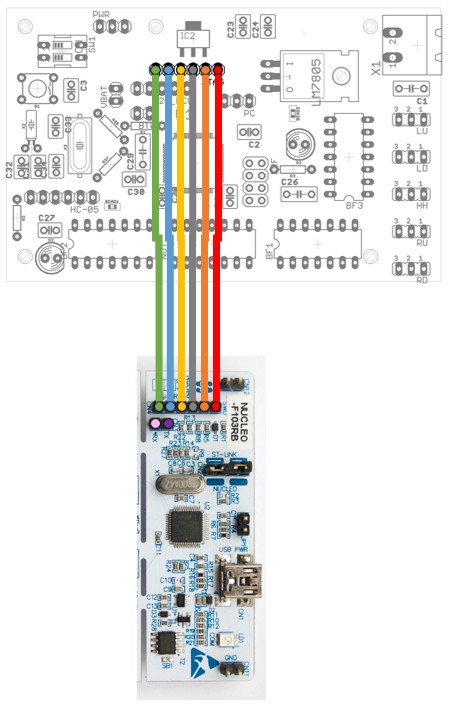
A programmer is a standalone module used to load code onto a microcontroller. All of ST's Nucleo boards come with an integrated programmer. We disassembled one such Nucleo board and have dedicated its programmer for use on the robot. It is typically kept in the robot's case. The image below is a visual guide on how to connect it to the PCB; the programmer is the bottom-most board. Note: as long as the programmer is connected to the PCB, it must be plugged into your computer for the microcontroller to function correctly. This is because the programmer holds the microcontroller in a reset state if it is not powered on.

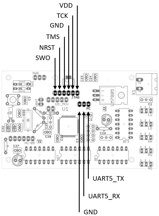
The image below is a reference showing the signals on each pin used for programming and communication.

The PC comm link is likely the only connection that will need to be made at the time of the test. The motors and IMU generally remain connected to the PCB. The soccer-pcb repository contains the schematics and layout files for the PCB, which can be viewed with the free version of the EDA tool Eagle. At the time of this writing, the folder containing the PCB files is STM32F446RE_subcircuit.
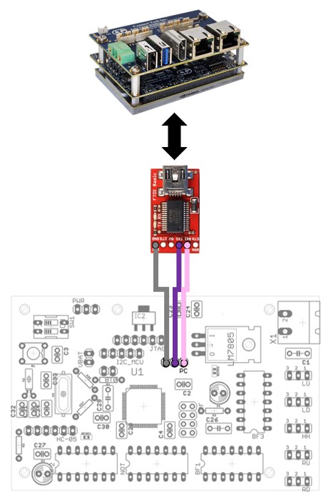
The image below shows how to connect the communication pins on the PCB to a UART to USB converter. Although the Jetson TX2 has native UART, we often test the embedded code from our own PCs (allowing us to debug and whatnot), so such a converter is necessary. Alternatively, the programmer can be used as a USB to serial converter as well, saving you 1 USB port. Referring to the diagram above and below, just connect pink to pink, purple to purple, and last but not least connect the grounds.

TODO (future development)
The robot should be supplied with 12.4 V. It is usually easiest to do this via a wall adapter, but a battery can also be used. Once the power supply is connected, turn it on by pressing the switch on the top of the torso.
When testing from a PC, open up soccer-communication/soccer_hardware_manual.py in your favourite Python IDE or text editor. Note: please see the wiki page on dealing with submodules if you intend to use the PC Communication folder from within soccer-embedded. In the __main__ block, set the COM port appropriately. This script loads a static trajectory, and every time you press enter, it sends a new column to the microcontroller and receives its response. Every so often, the sensor data is printed out on the screen. To change how frequently sensor data is printed out, edit the modulo divisor in receiveWithChecks(). Note that if you print out too frequently, PC-side performance will suffer.
Several trajectories can be tried if desired, but caution must be exercised as many of them correspond to big ranges of motion, which may alter the stability of the robot. One good test it to send the all 0 vector; this causes the robot to straighten all its limbs, which is a nice, stable position for it.
The soccer_hardware.py script can also be used. If testing on the Jetson, it should automatically work by default, including interfacing with ROS. You can run it from your own PC using the command python soccer_hardware.py --port=COM7 --ros=False and it will loop through the trajectory without involving ROS. Note that python soccer_hardware.py --help will print out the list of commands.
TODO - for now summarize what Robert has in the readme in the lwip folder in development/, and link to it for further details
Put things back the way you found them :)
Rough checklist:
- If runtime verification failed, program the old embedded program into the microcontroller before packing up
- Turn off robot
- Detach programmer
- Screw the back of the robot on
- Put power supply, screwdriver, and programmer back
- Put the robot back and secure the storage facility
Finally, merge the PR corresponding to the tests you ran if they were successful.
If access to the physical Robot, including Motors and any sensors not present on the development board, are not available, you can still verify your changes by sending input/output through the debugger USB connection. This verifies that the program, when loaded on the board, still communicates with the PC, and that FreeRTOS tasks are running as expected (i.e. not deadlocking). This requires access to the F4 or F7 board, a debugger for it, and a USB cable to connect the debugger to the PC.
To prepare the code, any references to huart5 must be replaced with references to the default debugger UART: huart2 (for the F4 board) or huart3 (for the F7 board). Do this vice-versa, so the two UART handles are effectively swapped. 3 files need to be edited: Common/app/freertos.cpp, Src/usart.c, Common/app/PeripheralInstances.cpp. Now, the debugger UART is used where the PC UART used to be.
Note that a full runtime test with all the equipment connected should be done before merging. The board-only runtime test serves only as a way to quickly verify that the critical program functionality is working.
- It is easy to forget to update one of the files listed with the swapped UART handles. When this happens, weird errors can occur, such as threads being notified at the wrong time. Both the references to the UART handle, and the configuration of that UART's hardware must be swapped.
grep -rn huart[123456]from inside theCommon,Robot_F4,Robot_F7is a quick way to see where all the handle references are. - Board-only testing is only verifying output, so it might look successful even if UART transmission is not configured in a way that will work once the rest of the application with the sensors etc. is operational. An example where this happened was when the
TxUART was configured to use polling mode, which was fine during board-only testing where the threads managing the motors and sensors were doing nothing anyway, but after trying in the robot with the sensors and motors connected, the other threads were in fact starved by the CPU time taken up byTxpolling. This was resolved after configuring theTxUART to use DMA, not polling.