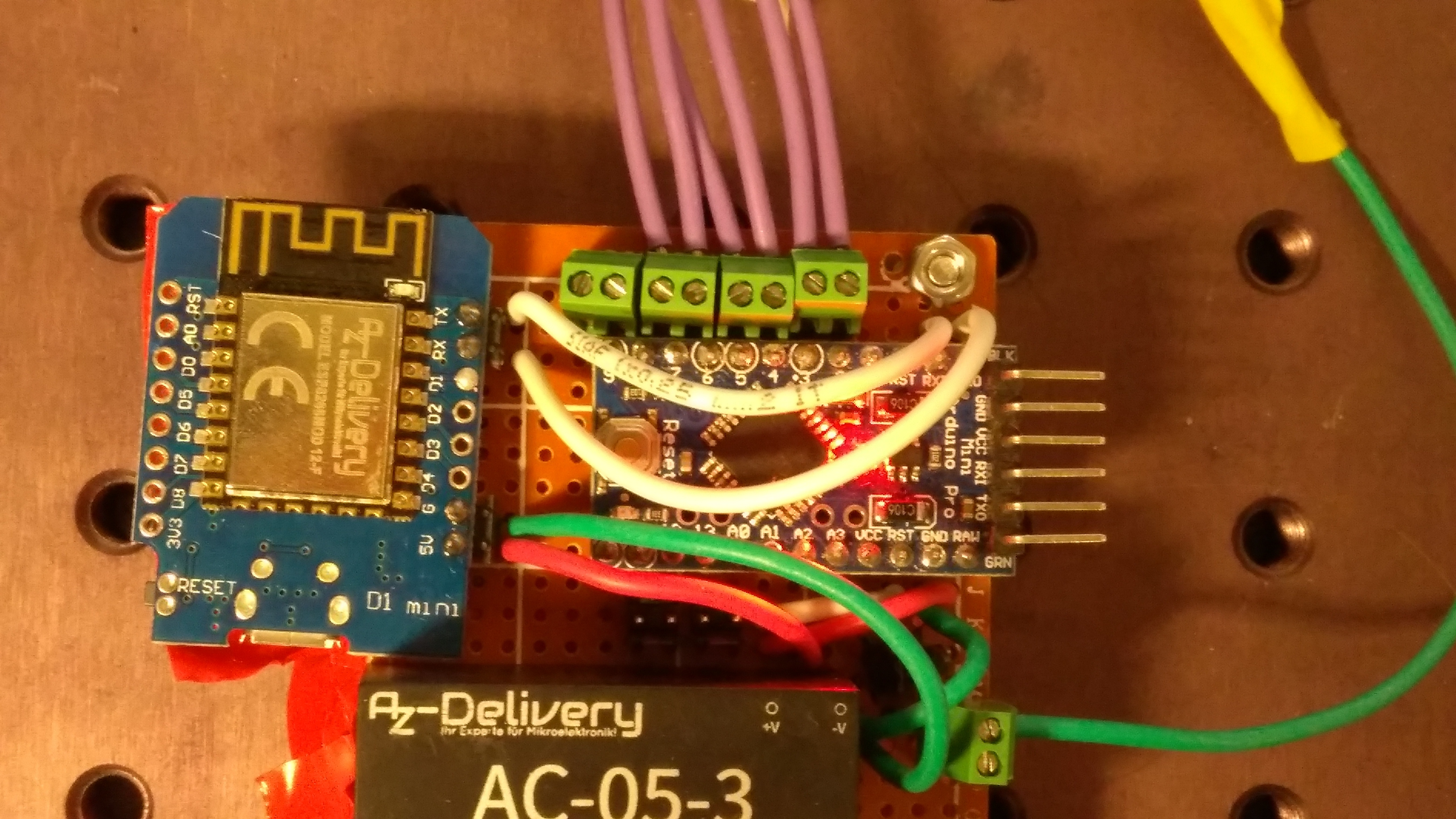
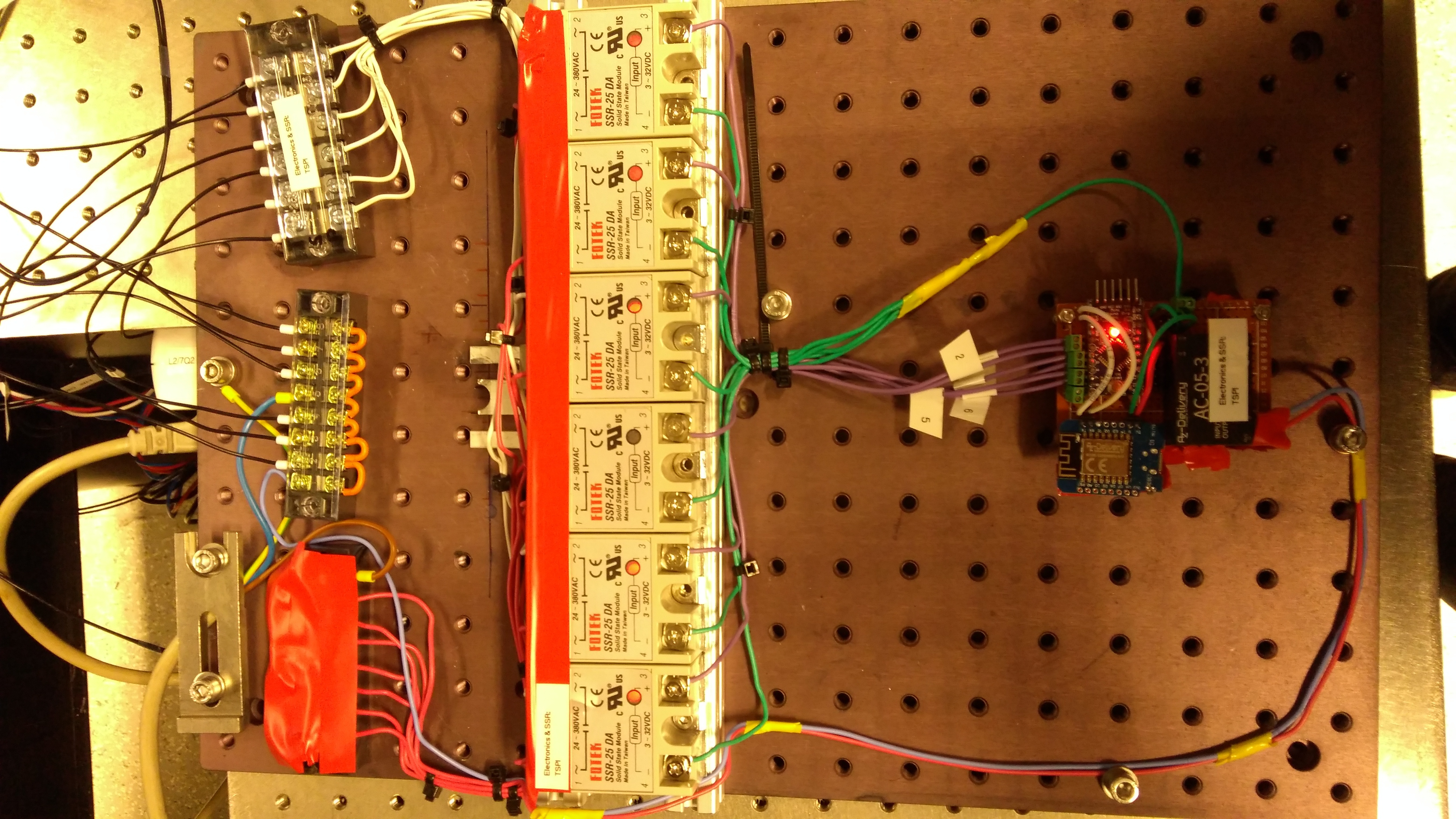
Currently this project contains sourcecode for an AVR and ESP8266 based PWM temperature controller - in it's current state it's a simple remote controlled PWM board that switches an array of SSRs to regulate the amount of electrical power supplied.
Since the control is done primary side on a pretty slow (thermal) system the PWM timeslice has been decided to be around 2 seconds (0.5 Hz) with a controllable duty cycle from 0-100 percent in 0.1 percent steps.
The PWM module works synchronously - on every iteration it simply checks if the next PWM clock cycle has elapsed (every 2 ms - i.e. every 40000 clock cycle thus I won't use a timer; introduces some jitter but for this application it's neglectable)
The project is based on simple firmware for an ATMega328P that performs PWM and talks to an external controller using it's serial port with the serial protocol described below.
A simple controller is supplied in ESP8266Controller that is designed to
run on an ESP8266 that is connected via WiFi to some network that allows one
to set parameters using a webinterface or MQTT. Currently MQTT is in development
and not fully functional though. Since this is rather easy this part uses the
Arduino framework for the ESP8266.
On first boot (or factory reset triggered by a button on GPIO0) the controller
spawns its own configuration WiFi that one can use to access the configuration
page on 192.168.4.1. After joining the WiFi the device is configured
using DHCP and is accessible via plain HTTP (no HTTPS) on port 80.
All serial messages start with at least a synchronization pattern 0xAA, 0x55.
After this comes a 1 byte length and 1 byte opcode field. The end of the packet
is always formed by a checksum - all bytes including the synchronization pattern
exclusively xor'ed should result in 0x00. The absolute minimum packet length
thus is 5 bytes.
| Offset | Length | Content |
|---|---|---|
| 0 | 2 | 0xAA, 0x55 |
| 2 | 1 | Length including length and opcode field as well as checksum and sync pattern |
| 3 | 1 | Operation code field |
| 4 | n-5 | Payload |
| n-1 | 1 | Checksum |
There is no terminator field since the next message starts with a synchronization pattern again.
| Code | Operation |
|---|---|
| 0x01 | Identify |
| 0x02 | Get channel count |
| 0x03 | Set duty cycle |
| Code | Response type |
|---|---|
| 0x01 | Error packet including 1 byte error code |
| 0x02 | Identify response |
| 0x03 | Get channel count response |
| Offset | Length | Content |
|---|---|---|
| 0 | 2 | 0xAA, 0x55 |
| 2 | 1 | Length (5) |
| 3 | 1 | OpCode 0x01 |
| 4 | 1 | Checksum |

