-
Notifications
You must be signed in to change notification settings - Fork 217
New issue
Have a question about this project? Sign up for a free GitHub account to open an issue and contact its maintainers and the community.
By clicking “Sign up for GitHub”, you agree to our terms of service and privacy statement. We’ll occasionally send you account related emails.
Already on GitHub? Sign in to your account
robot model for lbr_iiwa_7_r800 #117
base: melodic-devel
Are you sure you want to change the base?
Conversation
As suggested by @gavanderhoorn in #108, you can use Jade+ expressions in these macros such as
Strange indeed... is link_a6 the same regardless of the flange chosen? |
|
Oh, neat. I'll adjust this and #118 with this newfound macros knowledge and await further input on whether things are actually sane... I'll add one more check to the original question on materials/colors. |
Have you made any progress on this? Maybe ask Kuka? Is there the same issue with the 14? If so I can measure our physical robot as a sanity check but don't have access to a 7... |
|
@BrettHemes Just emailed them the summary of what I see. In doing so, I think it's an error in the manual.
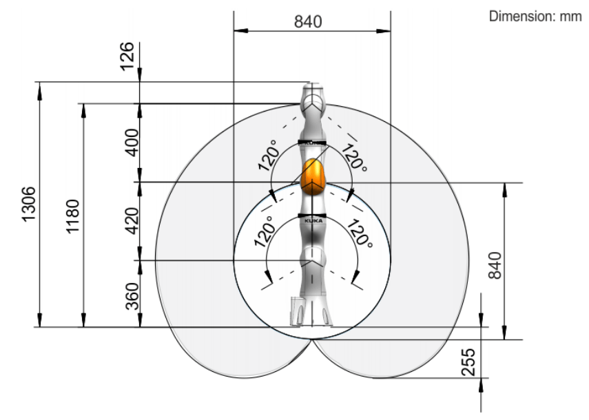
I wonder if the media flange drawing is correct (it matches the CAD) and there's a mistake in the regular iiwa manual. The issue also exists for the 14. Note the iiwa manual definition of the 1306mm dimension: And here's the media flange manual definition of the same 1306mm dimension: It can't be 1306mm from the |
|
I emailed Kuka and received a response:
Looking through the media flange options, it looks like Given this, any guidance on allowing the specification of a flange option in the |
|
If this is just a single parameter, you could add it with a default value to the macro. An alternative might be to actually make the flange a separate xacro macro. Seeing as there are so many of them, and they also all have different shapes, that might even make sense. A parameter for the macro modelling the main robot would then determine which of those gets attached. Or, robot + flange combinations could be provided in separate xacros that just tie two of them together (ie: a simple macro that combines the base robot with a particular media flange). Consumers of the macros would then use the combinations, instead of having to provide an argument. |
|
There are a few xacros of IIWAs available to the ROS community. It might be an idea to see how they approached this. |
|
@gavanderhoorn or @BrettHemes : could either of you nudge me in the right direction on this?
I'm not sure what's meant by this... search github? Is this a reference to a package repo I'm not aware of? I'm good on the color/materials and have the CAD for the pneumatic touch flange on both the R800 and R820. Once I have a definitive route on setting up the base robot ( Two options from above as I understand them:
Votes for either/or, preference for a different way, or suggestion on where the referenced community solutions are so I could take a look there? |
|
This now matches the framework used in the Other than that, these are identical now and can be built upon with additional flanges pretty easily. |
|
If the flange meshes are shared (which I imagine they are), I vote for putting these in a shared common folder a la the Agilus series (i.e., |
|
👍, waiting on #118 before working on getting this all wrapped up |
|
Hey guys, |
|
@chiliii I think we just need @gavanderhoorn to get enough time to take a look. I did 3 PRs around the same time and they are all sitting. |


This adds a robot model for the
lbr_iiwa_7_r800, attempting to address some of the joint origin requests noted in PR #31 .Please take a look and let me know of changes that would be helpful. This is my first robot model experience... some questions already:
CMakeLists.txtsomewhat significantly from what it was, which was quite different from the others I used as a reference. Please take a look there and see if that was correct._macro.xacroon the existing one for thelwr_iiwa_14_r820and I couldn't figure out how they calculated their joint limits. For example, joint A1 is +/- 170 deg.170*math.pi/180inpythonis 2.967, but 2.9668 was listed in ther820xacro, which does't match 170*3.[14159]/180 with any number of digits. Let me know if there is a common convention for digits/accuracy. Done: used${radians(foo)}macros per suggestion.kr3uses various defined materials, for example. Is red annoying to people? If so, is there a recommended generic material that's preferred?I interpreted this to mean it should be 1266mm from the base origin to the point of the Media Flange (MF) attachment, and that the final link length would be variable depending on the attachment type. The indicate a variable dimension, MF, in an odd place (it appears to be the entire last link). In addition, the actual model for the basic flange is 1266mm from the base to
tool0:The test launch file works fine, but I wanted to point this out anyway. It could be a nuisance for making this model more flexible with respect to the other media flange options.