I decided to write my programm with register instead standard Arduino Core libraries due very large memory consumption and required simple open-source LED-controller via UART interface. I will work with this project for simple christmas twinkling light with advance features (e.g. slow fade light and adjusable brightness light).
I don't like to use Arduino Core for big projects due large memory consumption and delay much time to change algorithm.
This project is sutiable for I/O pins manipluation via UART for computer/server which computers haven't built-in GPIO pins. Almost all modern computers have USB ports, so you need to connect to computer via UART bridge adapter from MCU. Computer software can maniplulate LED via UART interface, where most use in IoT devices. I can say that microcontroller is assumed is desktop's computer gpio pins. You can control relay, led, power motor and other than some actuators.
Picture of my assembles circuit
Screenshoot of sample command sending in serial port software
A project that led commands via UART in atmega328P popular MCU. In UART section code, we used based repository xanthium-enterprises/atmega328p-10bit-adc-configuration-code (algorithm and register configuration) in some portion of our code.
Futhermore, you can make own command via sending data from UART interface, so you need to sort myself to understand how work a function. Your code has included comments for explanation how work code. We'll add documenation and examples soon.
You can change led state via sending command in serial port ternimal and software. Note that you must send carriage return ASCII character after typing following commands. Carriage return is means that hit enter button in keyboard.
RED_LED_ON - Turn on red colour LED
RED_LED_OFF - Turn off red colour LED
GREEN_LED_ON - Turn on green colour LED
GREEN_LED_OFF - Turn off green colour LED
BLUE_LED_ON - Turn on blue colour LED
BLUE_LED_OFF - Turn off blue colour LED
ALL_LEDS_ON - Turn on all 3 LEDs
ALL_LEDS_OFF - Turn off all 3 LEDs
Hex value of carrige return - 0x0d. Decimal value of carrige return - 13.
If you enterred command other than list above, you will receive error message.
Serial port speed is 115200 bit per second, data frame is 8 bit, stop bit is one and no parity, so please setting to 115200 bps, 8N1, no parity.
You should use 14.7456 Mhz crystal oscillator for best working with UART inferface in microcontroller atmega328. Calculated baudrate via formula in Asynchronous normal mode UART, taking from datasheet. Value of UBRRn MUST BE INTEGER.
BAUD = fosc / 8(UBRRn + 1) and UBRRn = (fosc / (8 * BAUD)) - 1
UBRRn = (14745600 / (8 * 115200)) - 1 = 15
If I take 16Mhz crystal oscillator and I had need baudrate 115200 bps UART for this project.
UBRRn = (16000000 / (8 * 115200)) - 1 = 16.361111111111........ ~ 16.0 BAUD = 16000000 / (8(16 + 1)) = 117647.05...... bps ~ 117650 bps error = (117650 - 115200) / 115200 = 0.0212418301 ~ 0.0212 => 2.12 %
In conclusion, I choose exact frequecy of crystal oscillator where I received integer value of UBRRn, including use 14.7456 MHz crystal oscillator.
To order programm microcontroller, you need to have AVR programmer. (I had USB AVRISP XPII programmer)
USB AVRISP XPII programmer has support atmega328p MCU, according website link below.
See website instruction manual and list supported AVR MCU: https://www.waveshare.com/w/upload/DVD_AVR8_EN/data/product/USB_AVR_ISP_XPII_PG-1-1.htm
Please note that: this programmer ISN'T DEBUGGER TOOL and it is just programmer like ARDUINO UNO
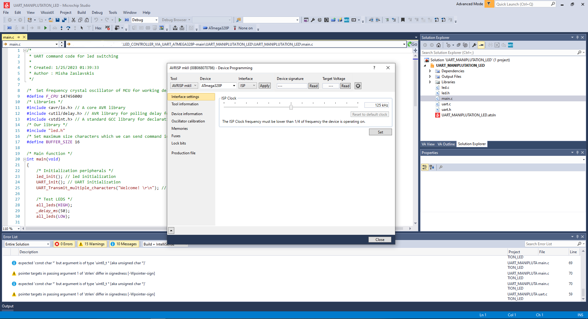
To programm this project, you need to go to tools from menu bar in top side and select Device programming.
In small pop-window called Device programming, you need select tool as AVRISP after connect to computer your USB AVRISP.
Choose interface as ISP and check button 'Apply' and check button 'Read' in both device signature and target voltage.
Select Memories in left side menu in pop window.
Click a button program
Finish to programm
Click close button in pop window after finished to program :)
Note: If appear error read device signature, you may be incorrect connect to programmer and MCU. Second reason fuse may be cause if you checked corrected connect to programmer and MCU. Incorrect programming fuse is caused permanently damage your AVR microcontroller or required fix your Atmega328 via unbricking MCU methods.
 Screenshoot Microchip Studio 7 IDE with opening pop window.
Picture of my USB AVRISP XPII programmer
Viewing repository and licence for related this project: https://github.com/xanthium-enterprises/atmega328p-serial-uart-to-pc-communication
Datasheet of microcontroller atmega328p: https://ww1.microchip.com/downloads/en/DeviceDoc/Atmel-7810-Automotive-Microcontrollers-ATmega328P_Datasheet.pdf
I/O - Input/Output
UART - Universal asynchronous receiver-transmitter.
LED - Light-emitting diode
MCU - Microcontroller unit
PCB - Printed Circuit Board
Thanks xanthium-enterprises repositor and author Rahul Sreedharan for understanding and studying how work UART register code. :)
Sreedharan, R. (2019, July 16th). ATmega238p to PC Serial Communication(RX/TX) using USART. Github. https://github.com/xanthium-enterprises/atmega328p-serial-uart-to-pc-communication/blob/master/_1_Serial_Transmit/main.c
Sreedharan, R. (2019, July 16th). ATmega238p to PC Serial Communication(RX/TX) using USART. Github. https://github.com/xanthium-enterprises/atmega328p-serial-uart-to-pc-communication/blob/master/_2_Serial_Receive/main.c
Sreedharan, R. (2019, July 9th). ATmega328P to PC Serial Communication using USART Tutorial. Github. https://www.xanthium.in/how-to-avr-atmega328p-microcontroller-usart-uart-embedded-programming-avrgcc


