-
Notifications
You must be signed in to change notification settings - Fork 1
2. Installation
To set up the Raspberry Pi, begin with flashing a standard image of Raspbian to an SD card. The project was coded and tested using Raspbian Lite with a Gnome Desktop and Raspbian Lite Buster, but any version of Raspbian should work.
For installing the operating system, the official Raspberry Pi Imager can be used. If you would like to install the Gnome desktop, the install will require that you have at least an 8GB SD card, the Pi plugged directly into a monitor, and a wifi or ethernet connection.
If you already have an OS installed in your Rasberry Pi, jump here
To use the Gnome desktop, first run
sudo raspi-config
Go into advanced options, select GL driver, install necessary packages if asked, and set the driver to fake KMS. Next, go back into advanced options and make sure you expand filesystem, as this is a large download. Then, back in bash, run
git clone https://github.com/TerraGitHuB/gnomeforpi.git && cd gnomeforpi && sudo bash gnomeforpi-install
This will take a long time. When the install is finished, the Raspberry Pi will reboot and you will be able to log into the Gnome desktop. In addition, the wifi will be disconnected, but you will be able to reconnect after logging in. After choosing your user and before entering your password, click the settings cog wheel under the password entry box and choose "Gnome for Xorg".
Next, you must enable the four hardware UARTs within the Raspberry Pi. Navigate to /boot/ and edit config.txt. At the end of the file, add on the following statements
force_eeprom_read=0
disable_poe_fan=1
dtoverlay=uart2
dtoverlay=uart3
dtoverlay=uart4
dtoverlay=uart5
The first two line disables the GPIO 0 and 1 functionality to be used for uart2. If you would like to use a hat or a POE fan with the Pi at the same time, remove the first three lines.
Now, you will be able to install or clone the Fedwatch github repository into your project and use the functions within it to run your own programs.
If you want the latest Github version, you can clone the repo
git clone https://github.com/RedSweatshirt/FEDWatcher.git
To connect the FED3 devices to the Raspberry Pi, you will need a cable that takes the BNC female from the FED3 (old version) or a 3.5 mm male jack to fit the 3.5 mm female jack (new version) and ends to interface with the Raspberry Pi (see below).
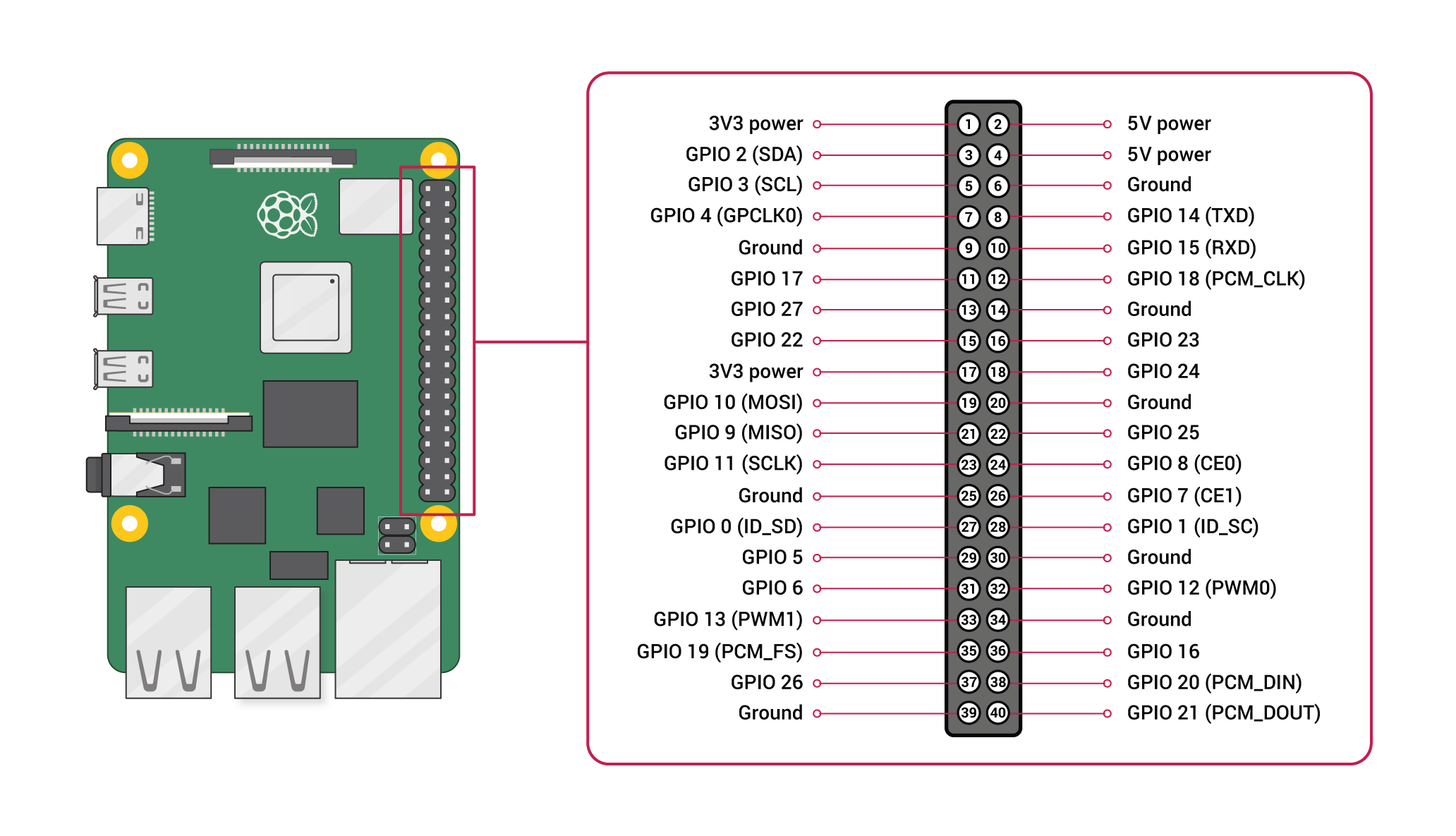
For this program, up to four FED3 devices can be hooked up to a single Raspberry Pi. There are four activated UART ports with receivers at GPIO pins 1, 5, 9, and 13, corresponding to port1, port2, port3, port 4, in order. The unused send pins are located at 0, 4, 8, and 12. These pins cannot be used while this program is running. However, if not all ports are used, they can be disabled in the setup function.
For this setup, the red/hot wire will go to one of the receiver post listed above, and the black/ground wire will go to any ground pin on the Raspberry Pi.
For more information on the pinout of the Raspberry pi visit the Official Raspberry Documentation. See below the official pinout for the Raspberry from the docs.

We are working on a friendly way to connect the output of FED3 devices (either BNC or 3.5mm Jacks) into the Raspberry Pi. Our current devices run using a prototype breakout board with this wiring.
