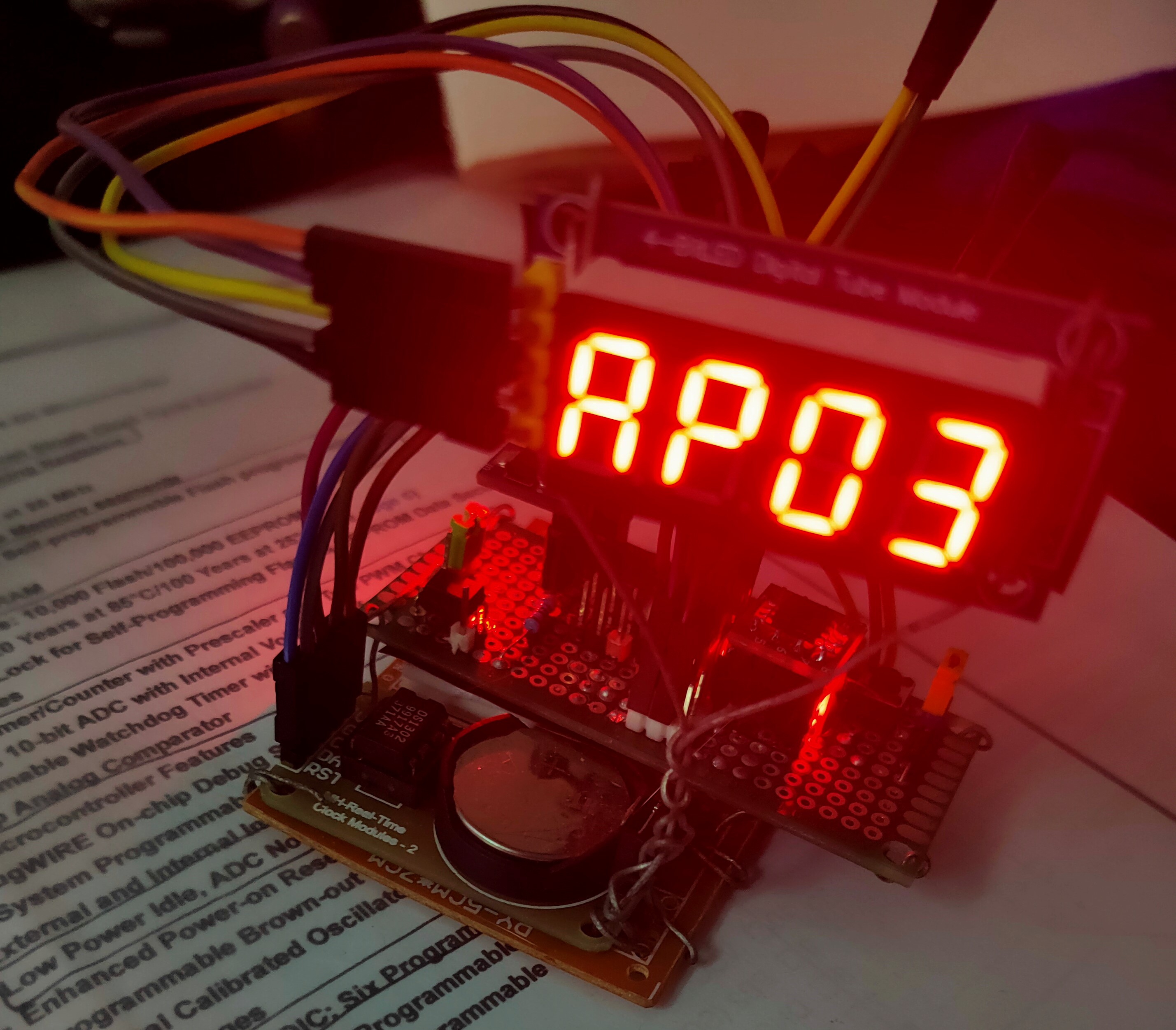
A digital clock with three buttons: A, B, and T.
- ATtiny13A.
- A DIY board with a push button of RESET.
- DS1302 RTC module.
- 4-bit 7-segment LED module, drived by two 74xx595 chips.
- Three additional push buttons used to config the clock, and a board to place them.
- USBasp or any other programmer.
- Atmel Studio 7.
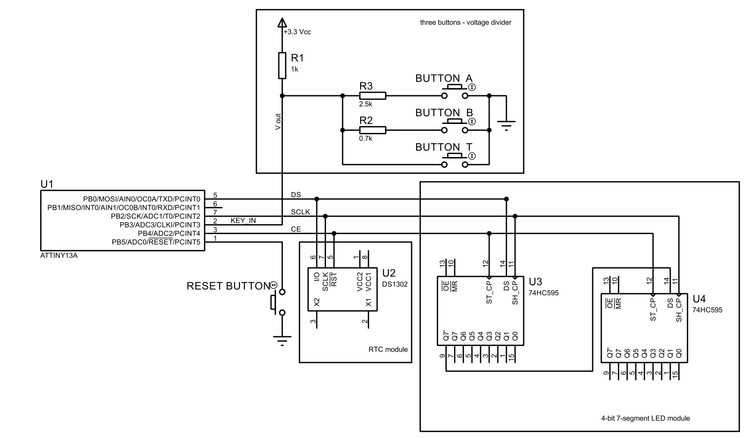
The circuit is pretty simple, here is the simplified diagram demonstrating the connections among main components:
Buttons are used to adjust time manually.
It will enter in time edit mode after the MCU reset, use button A and B to move editing position left and right and select which bit to edit, button T is used to increment the number at editing position.
Tiny13a has not enough IO pins to connect three buttons individually. Here is a trick which needs one wire only: the voltage divider circuit. The circuit output different voltage when a button is pressed, thus the button pressed can be figured out when the V_out is read by ADC. The ADC input pin is labeled KEY_IN.
These two modules are connected together to reduce IO occupation. The principal is that the DS1302 needs a steady high signal on CE line during operation, once the signal goes low the operation is terminated. While 595 only needs a positive pulse to output data in the shift register. The pulse can be short enough to avoid triggering DS1302 and SCLK and DS can remains high or low during the pulse, which means operation to 595 will not interfere DS1302.
Of course the data in 595 will be messed up when transferring data with DS1302, it doesn't matters, you just write again after the transfer is done.
Hour is displayed as a hex number, thus 'A' means 10 clock. A mark of AM/PM showed to the right, and minute is two decimal numbers.
You can see there is still a pin remains unconnected, which allows further expansion, as long as the flash space is enough ...
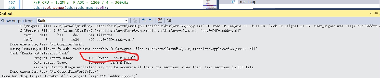
which has only 4 bytes left.
If you use ATtiny25 or higher, an alarm feature should be easily implemented.
And what is that aaz stuff ? That is a thin wrap library which hides mostly all special register operations behind inline functions with zero overhead, to cure the pain of my human memory and enhance the readability, I hope.