Add tutorials for ApplyForceTorque and MouseDrag plugins #2083
There are no files selected for viewing
This file contains bidirectional Unicode text that may be interpreted or compiled differently than what appears below. To review, open the file in an editor that reveals hidden Unicode characters.
Learn more about bidirectional Unicode characters
This file contains bidirectional Unicode text that may be interpreted or compiled differently than what appears below. To review, open the file in an editor that reveals hidden Unicode characters.
Learn more about bidirectional Unicode characters
| Original file line number | Diff line number | Diff line change |
|---|---|---|
| @@ -0,0 +1,116 @@ | ||
| \page apply_force_torque Apply Force and Torque | ||
|
|
||
| The Apply Force Torque plugin allows users to apply forces and/or torques to | ||
| links in the simulation through the graphical user interface. | ||
|
|
||
| ## Examples | ||
|
|
||
| Let's go through an example of applying force and torque to simple models. Open | ||
| the `shapes.sdf` world with | ||
|
|
||
| ```bash | ||
| gz sim shapes.sdf | ||
| ``` | ||
|
|
||
| From the plugin dropdown, select the `Apply Force Torque` plugin. Make sure the | ||
| simulation isn't paused. | ||
|
|
||
|  | ||
|
|
||
| ### Apply force to a link | ||
|
|
||
| We want to apply force to the `cylinder` model. Select the model, either by | ||
| clicking on it in the scene or through the Entity Tree. If the model had | ||
| multiple links, we could select through the interface which one to apply the | ||
| force to (in this case, `cylinder_link`). | ||
|
|
||
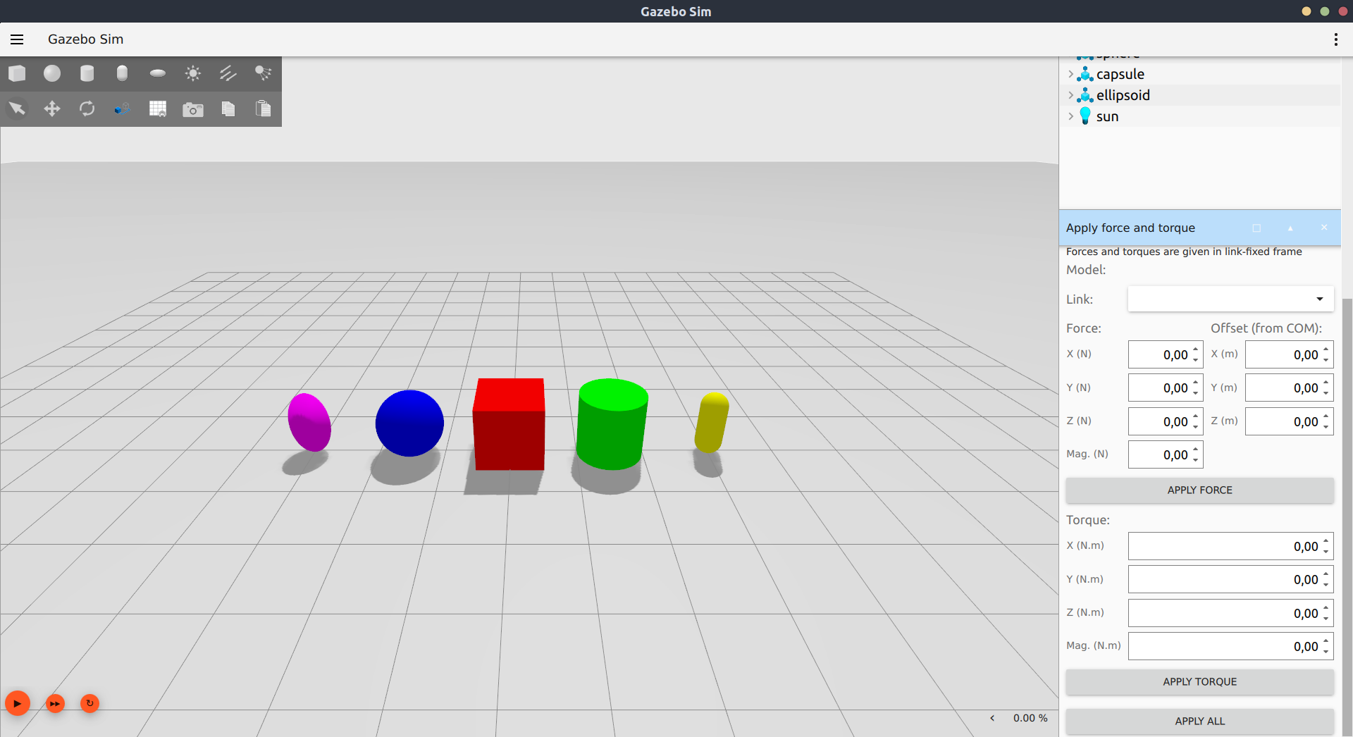
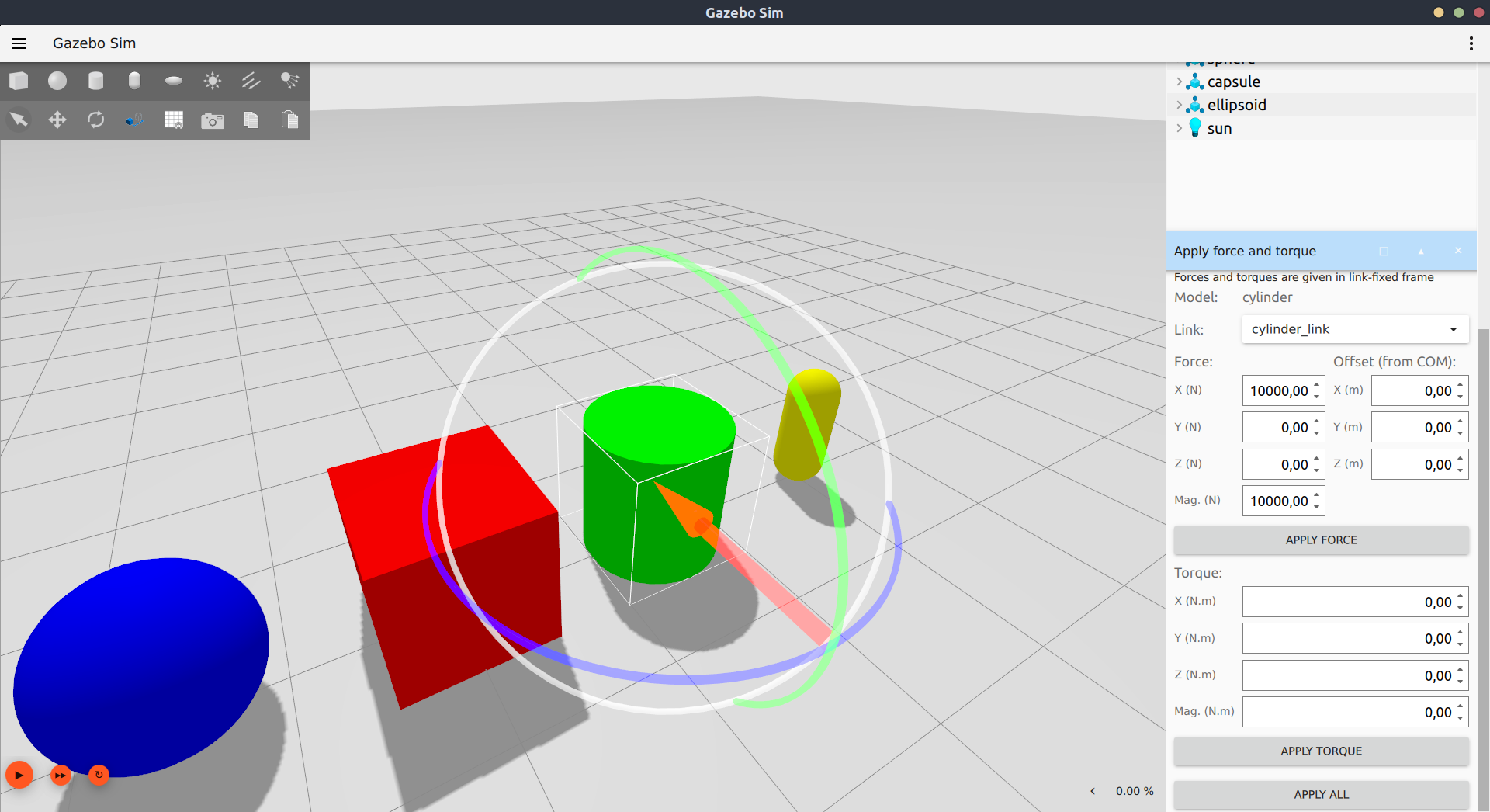
| On the dialog, write `10000` on the `X` field under `Force` and click on | ||
| `Apply Force`. The cylinder will be pushed on the X direction. The force was | ||
| applied in the link's `X` direction for a single time-step, which is in the | ||
| order of milliseconds, thus the need for such a large force. | ||
|
|
||
|  | ||
|
|
||
| ### Apply torque to a link | ||
|
|
||
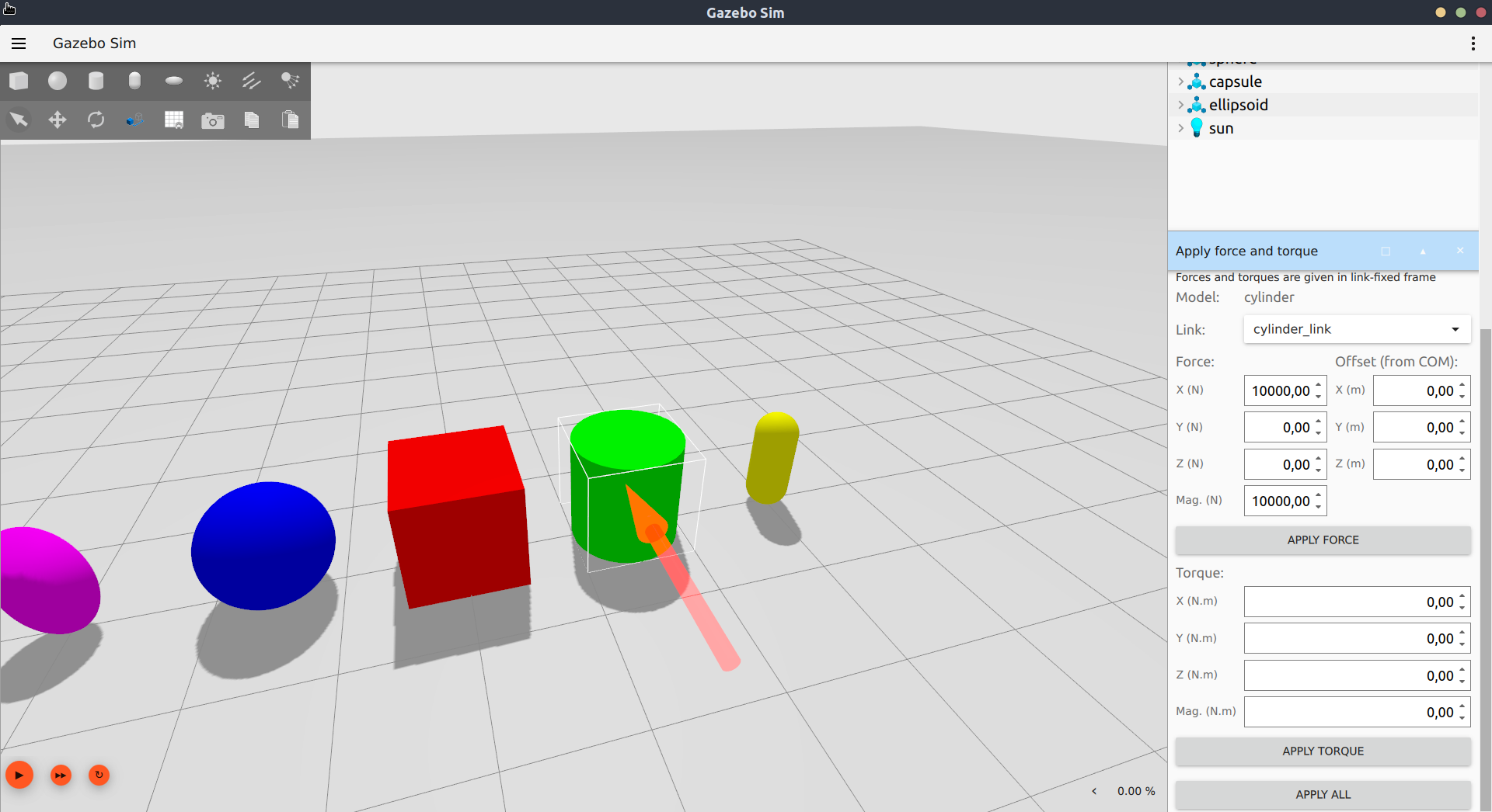
| On the dialog, write `2000` on the `X` field under `Torque` and click on | ||
| `Apply Torque` to see the cylinder rotate slightly. | ||
|
|
||
|  | ||
|
|
||
| ### Apply force with an offset | ||
|
|
||
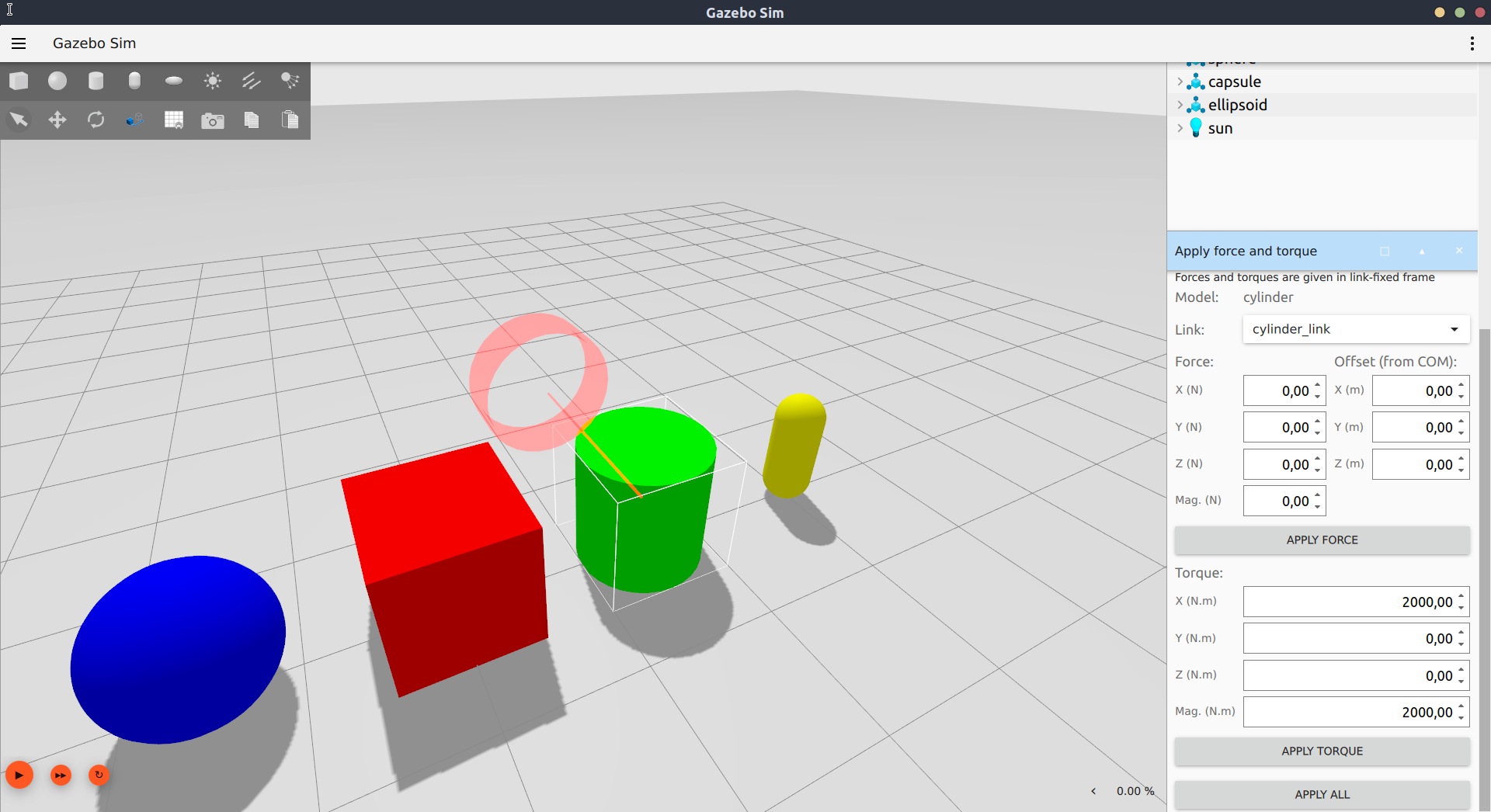
| By default, the force is applied to the link's center of mass, but this can be | ||
| modified through the `Offset` fields. On the dialog, write `1000` on the `X` | ||
| field under `Force` and `1` under the `Z` field under `Offset`. Press | ||
| `Apply Force` to see the model move slightly in the `X` direction while also | ||
| rotating around the `Y` direction. | ||
|
|
||
|  | ||
|
|
||
| ### Rotation tool | ||
|
|
||
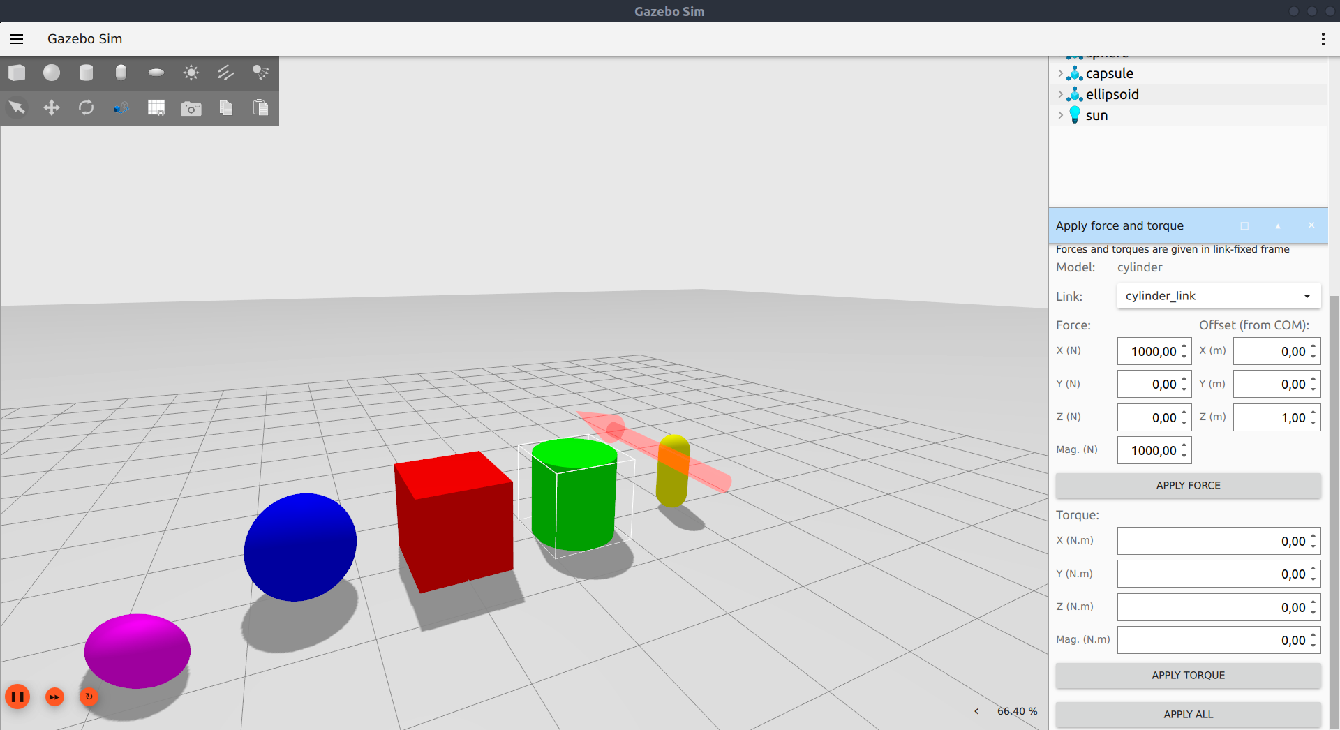
| On the dialog, write `10000` on the `X` field under `Force`. Click on the force | ||
| vector to make the rotation tool appear. Drag the blue circle to rotate the | ||
| force around the `Z` axis so that it is aligned with the `Y` direction. Notice | ||
| how the XYZ fields changed, but not the magnitude. Press `Apply Force` to see | ||
| the model move in the `Y` direction. | ||
|
|
||
|  | ||
|
|
||
| ## The interface explained | ||
|
|
||
| > **Note**: If you apply force and/or torque while the simulation is paused, | ||
| they will accumulate and be applied all at once when the simulation is | ||
| unpaused. | ||
|
|
||
| ### Force | ||
|
|
||
| - **Force X, Y, Z**: Each field specifies how much force will be applied on that | ||
| direction, in Newtons (N). The frame is fixed to the link. | ||
|
|
||
| - **Mag**: The total magnitude of the force which will be applied, which is the | ||
| Euclidean norm of the 3 forces above. Changing the magnitude changes the XYZ | ||
| fields proportionally, maintaining the force direction. | ||
|
|
||
| - **Offset X, Y, Z**: By default, force is applied to the link's center of mass, | ||
| in meters. Here you can edit the X, Y and Z fields to give the force an offset | ||
| with respect to the center of mass expressed in the link's frame. | ||
|
|
||
| - **Tip**: Right-click the model and choose `View` -> `Center of Mass` to see | ||
| its position. You will want to also make the model transparent to see the | ||
| center of mass visual (`View` -> `Transparent`). | ||
|
|
||
| - **Apply Force**: Click this to apply only force for one time step. Keep in | ||
| mind that time steps are typically in the order of milliseconds, so relatively large | ||
| forces are needed in order to apply a significant impulse. | ||
|
|
||
| ### Torque | ||
|
|
||
| - **X, Y, Z**: Each field specifies how much torque will be applied about that | ||
| axis, in Newton-meters (N.m). The frame is fixed to the link. | ||
|
|
||
| - **Mag**: The total magnitude of the torque which will be applied, which is the | ||
| Euclidean norm of the 3 torques above. Changing the magnitude changes the XYZ | ||
| fields proportionally, maintaining the torque direction. | ||
|
|
||
| - **Apply Torque**: Click this to apply only torque for one time step. Keep in | ||
| mind that time steps are typically in the order of milliseconds, so relatively large | ||
| torques are needed in order to apply a significant angular impulse. | ||
|
|
||
| - **Note**: Torque is always applied about the center of mass. | ||
|
|
||
| ### Apply All | ||
|
|
||
| Force and torque are applied at the same time, i.e. apply a wrench. | ||
|
|
||
| ### Rotation Tool | ||
|
|
||
| The vector (force or torque) directions will always match the directions | ||
| specified in the dialog. From the dialog, the direction can be changed by | ||
| editing the numbers on the XYZ fields. | ||
|
|
||
| From the scene, select a vector to enable the rotation tool, then drag the | ||
| handles. This changes the direction of the vector, updating the XYZ fields | ||
| accordingly without modifying its magnitude. You may click again on the vector | ||
| to unselect the rotation tool. | ||
Loading
Sorry, something went wrong. Reload?
Sorry, we cannot display this file.
Sorry, this file is invalid so it cannot be displayed.
Loading
Sorry, something went wrong. Reload?
Sorry, we cannot display this file.
Sorry, this file is invalid so it cannot be displayed.
Loading
Sorry, something went wrong. Reload?
Sorry, we cannot display this file.
Sorry, this file is invalid so it cannot be displayed.
Loading
Sorry, something went wrong. Reload?
Sorry, we cannot display this file.
Sorry, this file is invalid so it cannot be displayed.
Loading
Sorry, something went wrong. Reload?
Sorry, we cannot display this file.
Sorry, this file is invalid so it cannot be displayed.
Loading
Sorry, something went wrong. Reload?
Sorry, we cannot display this file.
Sorry, this file is invalid so it cannot be displayed.
Loading
Sorry, something went wrong. Reload?
Sorry, we cannot display this file.
Sorry, this file is invalid so it cannot be displayed.
Loading
Sorry, something went wrong. Reload?
Sorry, we cannot display this file.
Sorry, this file is invalid so it cannot be displayed.
This file contains bidirectional Unicode text that may be interpreted or compiled differently than what appears below. To review, open the file in an editor that reveals hidden Unicode characters.
Learn more about bidirectional Unicode characters
| Original file line number | Diff line number | Diff line change |
|---|---|---|
| @@ -0,0 +1,66 @@ | ||
| \page mouse_drag Mouse Drag | ||
|
There was a problem hiding this comment. There was a problem hiding this comment. Done in 8a4afa7 |
||
|
|
||
| The Mouse Drag plugin allows the user to exert forces and/or torques by dragging | ||
| objects in the scene with the mouse cursor. It has two modes: rotation and | ||
| translation. | ||
|
|
||
| To use it, open any world (such as `shapes.sdf`) and select `Mouse Drag` from | ||
| the plugin dropdown to load the plugin. | ||
|
|
||
|  | ||
|
|
||
| ## Rotation mode | ||
|
|
||
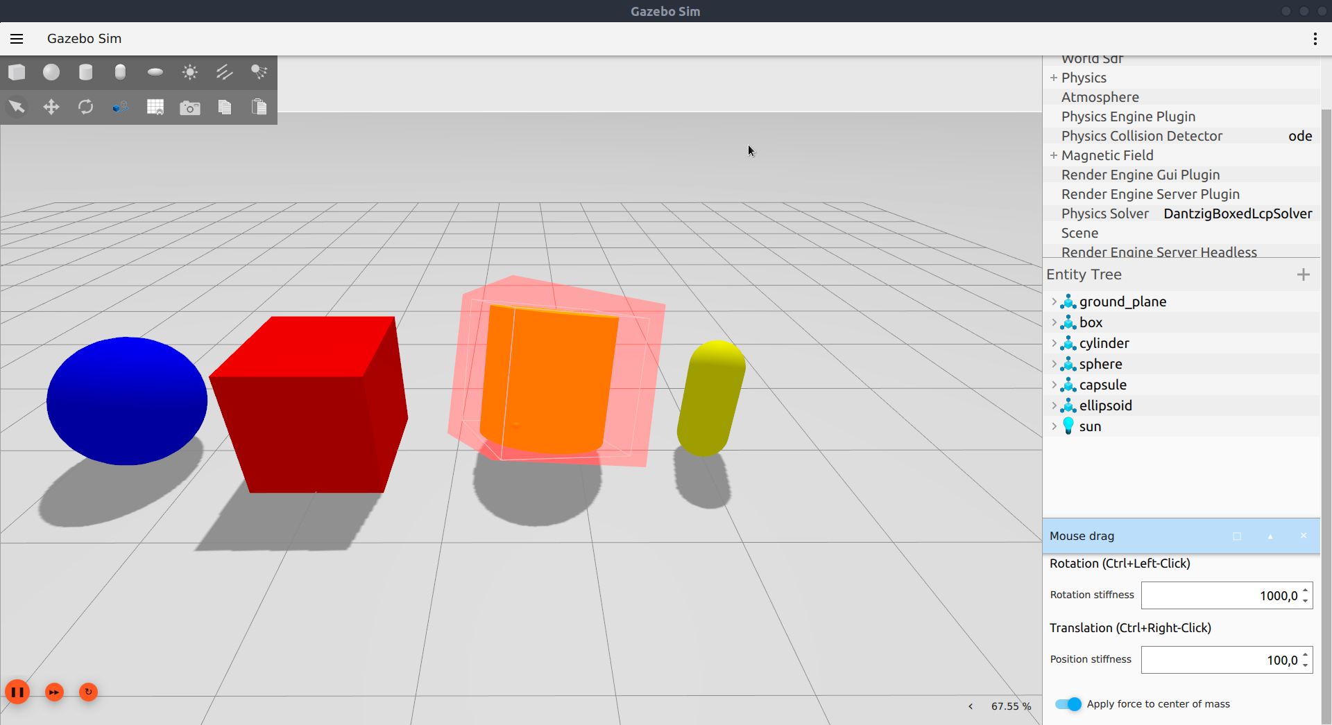
| The rotation mode is activated by Ctrl+Left-clicking and holding a link in the | ||
| scene. Dragging the mouse causes a pure torque to be applied, contained in a | ||
| plane parallel to the camera. The transparent red bounding box displays the | ||
| desired orientation of the link corresponding to the current mouse position. | ||
|
|
||
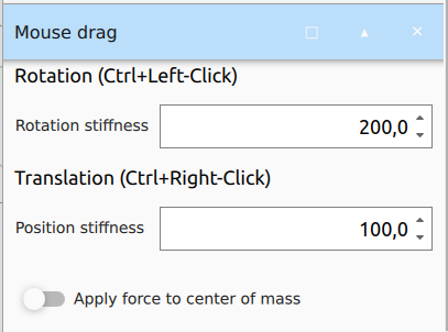
| The magnitude of the torque is calculated by a spring-damper system with a | ||
| constant stiffness and critical damping. It is also proportional to the link's | ||
| inertia, so that the same stiffness causes similar effects on different links. | ||
| The rotational stiffness can be modified through the interface. | ||
|
|
||
|  | ||
|
|
||
| ## Translation mode | ||
|
|
||
| The translation mode is activated by Ctrl+Right-clicking and holding a link in | ||
| the scene. Dragging the mouse will then move the link towards the mouse | ||
| position. On the interface, you may select whether the force should be applied | ||
| to the link's center of mass or to the point where the mouse click occured. | ||
|
|
||
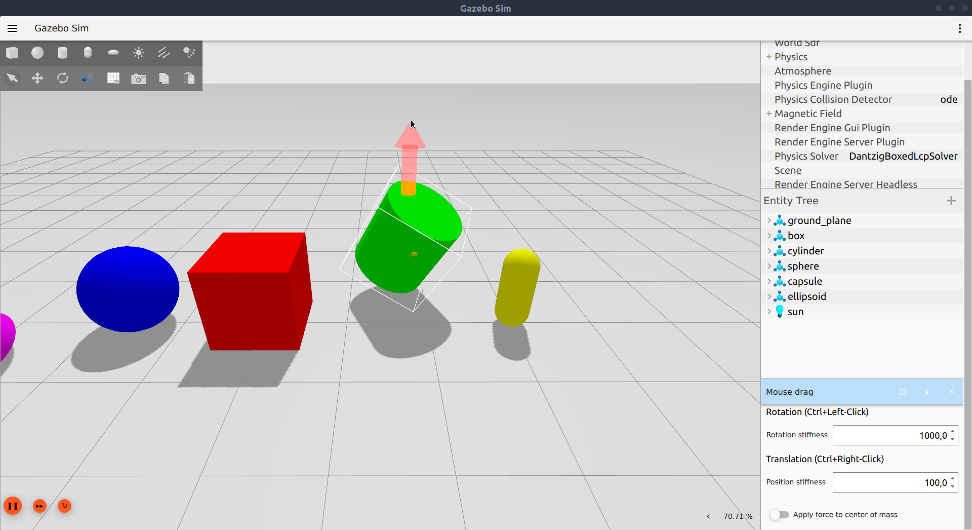
| If center of mass is selected, only a force is applied, with a magnitude given | ||
| by a constant stiffness and critical damping, scaled by the mass of the link. | ||
| The force is always contained in a plane parallel to the camera and passing | ||
| through the application point, represented by a transparent gray plane. The | ||
| visualization also shows an arrow from the application point to the target | ||
| position under the mouse cursor. | ||
|
|
||
| If center of mass is not selected, an additional torque is applied to account | ||
| for the offset in the force application point. In this case, the rotation of | ||
| the object is also slightly damped (according to the rotational stiffness). | ||
| The position stiffness can be modified through the interface. | ||
|
|
||
|  | ||
|
|
||
| ## SDF configuration | ||
|
|
||
| The rotation and position stiffness may also be configured in the SDF file. | ||
| To do this, add the `<rotation_stiffness>` and/or `<position_stiffness>` to the | ||
| plugin element under `<gui>`. | ||
|
|
||
| ```xml | ||
| <sdf version="1.6"> | ||
| <world name="mouse_drag"> | ||
| <gui> | ||
| <plugin filename="MouseDrag"> | ||
| <rotation_stiffness>100.0</rotation_stiffness> | ||
| <position_stiffness>100.0</position_stiffness> | ||
| </plugin> | ||
| ... | ||
| </gui> | ||
| ... | ||
| </world> | ||
| </sdf> | ||
| ``` | ||
Add this suggestion to a batch that can be applied as a single commit.
This suggestion is invalid because no changes were made to the code.
Suggestions cannot be applied while the pull request is closed.
Suggestions cannot be applied while viewing a subset of changes.
Only one suggestion per line can be applied in a batch.
Add this suggestion to a batch that can be applied as a single commit.
Applying suggestions on deleted lines is not supported.
You must change the existing code in this line in order to create a valid suggestion.
Outdated suggestions cannot be applied.
This suggestion has been applied or marked resolved.
Suggestions cannot be applied from pending reviews.
Suggestions cannot be applied on multi-line comments.
Suggestions cannot be applied while the pull request is queued to merge.
Suggestion cannot be applied right now. Please check back later.
There was a problem hiding this comment.
Choose a reason for hiding this comment
The reason will be displayed to describe this comment to others. Learn more.
I think you'll need to add a link to this page in https://github.com/gazebosim/gz-sim/blob/gz-sim7/tutorials.md.in