This project refers to the article Un trittico vincente: ESP32, Raspberry Pi e EMQ X Edge published on Antonio Musarra's Blog
This project contains the source code to be installed on the ESP32 devices that are part of the IoT solution described by the article mentioned above.
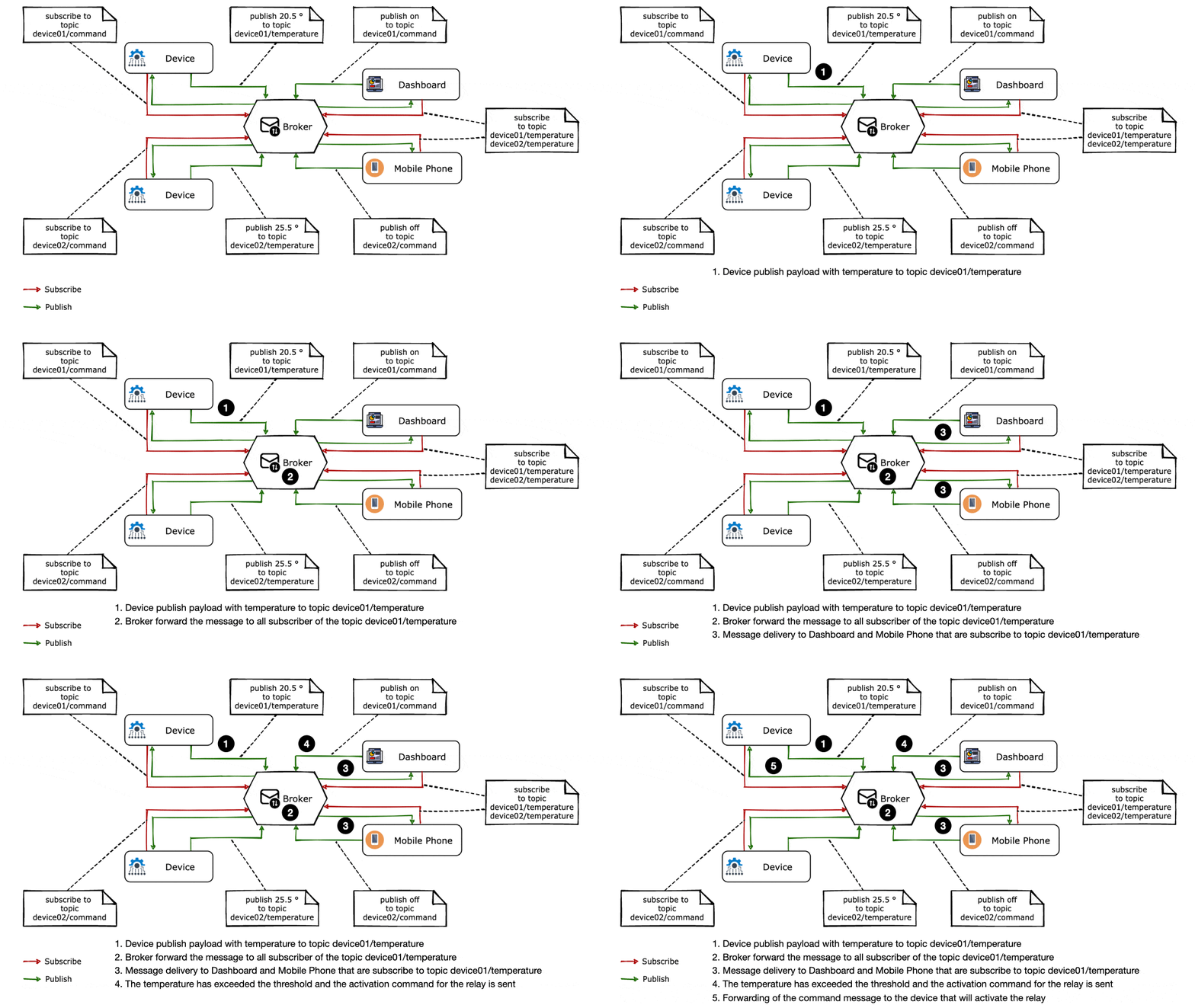
It's easy to understand how things work with a simple diagram, and the one below shows two devices (ESP32), a dashboard and a mobile phone. In this case and in the context of the Publish/Subscribe pattern, these components take on the role of both publisher and subscriber, and the broker is the message dispatcher.
The Dashboard and the Mobile Phone indicate to the broker that they want to
subscribe to all the messages that belong to the topic device01/temperature and
device02/temperature. This means that they will receive all the messages
published by the devices (device01 and device02) on their respective topics.
The Dashboard and the Mobile Phone publish "command" messages on the two topics
device01/command and device02/command, the respective devices are subscribed
to these two topics and will then receive the commands to activate or deactivate,
for example, relays or actuators.
Figure 1 - Animation showing the Publish/Subscribe architectural style in action
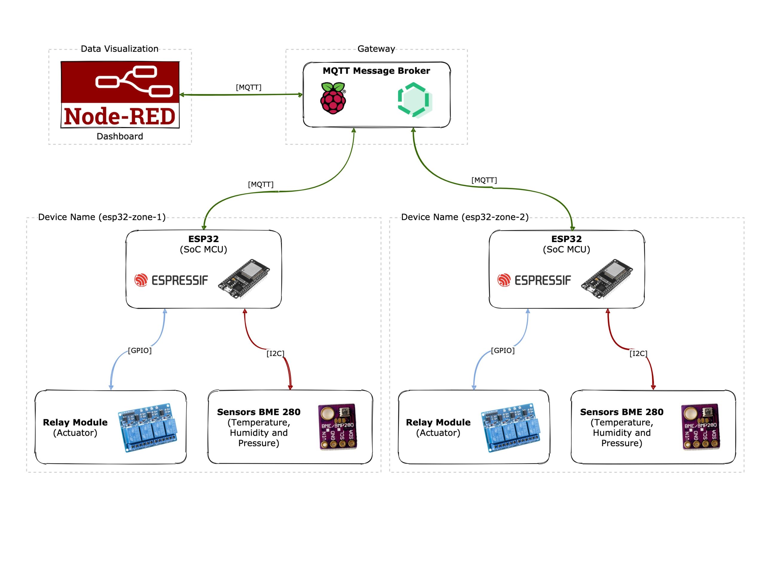
The common dialect used for communications between Gateway, Device and Dashboard is the MQTT. The ESP32 communicates with the environmental sensor via the I2C bus, while to pursue actions towards the relay module it uses four GPIO channels.
Figure 2 - Architecture of the IoT solution with evidence of hardware and software components
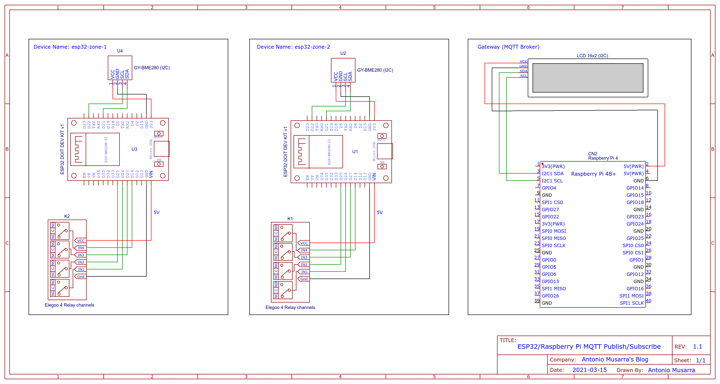
To implement this solution from the hardware point of view, we need to know how to make the connections between the pieces of "iron" so that everything can work correctly. The wiring diagram shows the connections concerning the device, then the BME 280 sensor and the relay module to the ESP32 DOIT DEV KIT development board (30-pin). The diagram also shows the connection of the Gateway with a 16 × 2 LCD display, inserted with the aim of showing the environmental data and the status of the relays, information whose source is represented by each device.
Figure 3 - Electrical diagram of the hardware components that make up the IoT solution
The development board of the ESP32 is equipped with a Micro-USB port for powering the module itself and uploading the firmware. This development board supports automatic upload, so it will not be necessary to manually change the upload and execution mode when it is necessary to upload the new software.
ESP-IDF is Espressif's official IoT development framework for the ESP32 and ESP32-S series of SoCs. It provides a self-contained SDK for any generic application development on these platforms, using programming languages such as C and C ++. ESP-IDF currently powers millions of devices in the field and allows you to build a variety of networked products, ranging from simple light bulbs and toys to large appliances and industrial devices.
For this solution, however, I chose to adopt the Arduino framework based on Wiring , for three simple reasons: simple to use, extensive documentation and widely disseminated and known .
Will we then use the classic Arduino IDE programming environment? No, I propose something different.
I have always been of the idea that from the moment a software project is created, as far as possible, it is better not to link it to a specific IDE (Integrated Development Environment). I like the fact that the projects are independent from the IDE, I have to be able to build the project from the command line: git clone, build and install .
The something else is PlatformIO . It is a cross-platform, cross-architecture , multiple-framework : a tool for embedded systems engineers and software developers who write applications for embedded products.
Without going too deeply into the implementation details of PlatformIO, the work cycle of the project developed using PlatformIO is as follows:
The development boards involved are chosen by specifying them in the platformio.ini file (project configuration file). Based on this list of boards, PlatformIO downloads the required toolchains and installs them automatically. The development of the code begins and PlatformIO makes sure that it is compiled, prepared and loaded on all the cards of interest. To write the code you can use your favorite editor or IDE, alternatively you can use PlatformIO for VSCode . The only requirement is the installation of PlatformIO Core (CLI) on your development machine. PlatformIO Core is written in Python and therefore works on Windows, macOS, Linux, FreeBSD and ARM- based credit-card sized computers ( Raspberry Pi , BeagleBone , CubieBoard , Samsung ARTIK , etc.).
The minimum version of PlatformIO Core to install is version 5.x. If you have already installed a version of PlatformIO, you can upgrade through the command pio upgrade.
Now that we have chosen PlatformIO as a software development support tool, we can move on to analyze the developed code.
The main responsibilities for the software to be created for the ESP32 are: the reading of environmental data and the subsequent publication on the topic esp32/telemetry_data through the Message Broker, as well as receiving the commands from the topic esp32/command and the subsequent execution of the same. The macro responsibilities are indicated below.
-
I2C setup for the GY-BME280 sensor
-
GPIO setup for relays
-
Setup of the connection to the WiFi network
-
Setup of the connection to the MQTT Message Broker
-
Reading of environmental data from the GY-BME280 sensor
-
Preparation of the message with the environmental data in JSON format
-
Preparation of the message with the relay status data in JSON format
-
Publication of environmental data via MQTT
-
Publication of the relay status via MQTT
-
Reading and execution of commands arriving on the topic esp32/command
The basic functions of the esp32_mqtt_publish_subscribe.cpp program are:
- void setup_wifi() : the responsibility of this function is to establish the connection to the WiFi network. The connection parameters (SSID and username) can be set during the build phase; later we will see how. The WiFi network to which we must connect the devices must guarantee connectivity to the Message Broker;
- void reconnect() : the responsibility of this function is to establish the connection to the Message Broker and manage any reconnections, for example in cases where the connection to the WiFi network fails. Immediately after the connection to the Message Broker, the topic is subscribed to esp32/command with QoS equal to one and the initialization of the relay status to off;
- void update_relay_status(int relayId, const int status) : the responsibility of this function is to update the status of the relays by publishing messages on the related topics esp32/releay _ $ {id} _status;
- int * get_relays_status() : the responsibility of this function is to return an array of four elements containing the status of the relays whose values can be: 0 for off and 1 for on;
- void callback(char * topic, byte * message, unsigned int length) : this is the callback function called whenever a message is received on the topic for which you have an active subscription and in this case the topic for which there is a active subscription is esp32/command. The responsibility of this function is to acquire the messages arriving on the esp32/command topic, parse the received command and perform the corresponding action which can be: activate/deactivate the relay or publish the relay status.
By adopting the Arduino framework, we also carry the mandatory setup() and loop() functions . The setup() function is executed only once, at start-up, and the body of this function foresees:
- initialization of the serial communication interface ;
- initialization of the logging framework;
- initialization and check of the I2C channel for the BME280 sensor;
- initialization of the clientId variable used to identify the device as a client in the MQTT connection to the Message Broker;
- initialization of the connection to the WiFi network;
- pin mode initialization for relays (or actuators);
- initialization of the state of the relays (via digitalWrite() bringing them all four to the deactivated state;
- initialization of the NTP Client (with UTC timezone).
The loop() function is instead executed in "continuation" and the body of this function provides:
- time client update via NTP;
- control of the connection to the Message Broker and possible recession;
- calling the loop() method on the MQTT client to allow processing of incoming messages and maintain connection to the server;
- preparation of the message in JSON format that contains the environmental data coming from the BME280 sensor;
- publication of environmental data on the topic esp32/telemety_data;
- sending of the published JSON message on the serial line (for debugging purposes)
Building the project is quite simple and just the way I like it: git clone and build . Remember that before proceeding further, the required requirement is the installation of PlatformIO Core on your development machine.
Until now we have not made any reference to how to configure the access parameters to the WiFi network and the Message Broker. What must be done to configure the access parameters to the WiFi network and the Message Broker?
In these cases, I usually prefer to follow the path of build flags . These flags affect the pre-processor, compilation, assembly, and linking processes for C and C ++ code. All compiler and linker flags can be used. In this case we will use the build flag -D name = definition which affects the CPPDEFINES build variable . The contents of the definition are tokenized and processed as if they appeared during the third translation stage in a #define directive. For more information I invite you to read C preprocessor .
At the beginning of the esp32_mqtt_publish_subscribe.cpp source code there are the various ifdef… endif sections for reading all the build flags. The build flags defined on the project's platformio.ini file are shown below . Among the build flags, in addition to those concerning the access parameters to the WiFi network and the Message Broker, we also have a build parameter that sets the name of the device. Note that the values of these parameters come from their environment variables.
Before continuing with the compilation process, it is therefore necessary to set the environment variables indicated above. Since we have two devices on which to install the software, we are careful to modify the DEVICE_NAME environment variable . This environment variable can take the following values: esp32-zone-1 and esp32-zone-2. The device name information is reported on the JSON message that contains the environmental data.
Below are the commands necessary to complete the compilation of the project and thus generate the artifact ( firmware.bin ) which will subsequently be installed on the ESP32 device.
During the build process, PlatformIO also downloads the libraries on which the project depends and which are indicated in the lib_deps section of the platformio.ini file (see also Table 5).
The Compiling the ESP32 MQTT Publish/Subscribe project with PlatformIO screencast is shown below so that you can see exactly the execution of the steps indicated above.
We have reached the final step for what concerns the ESP32 devices, that is, the upload of what can also be called the firmware of our devices. The upload operation is always assigned to PlatformIO using the simple command: pio run --target upload --environment esp32dev. The same operation can also be performed through the IDE.
In reality it is also possible to skip the project compilation process, the upload process, if necessary, will start the compilation of the code and then continue with the upload on the ESP32.
The Upload software to ESP32 Device via PlatformIO screencast is shown below so that you can see exactly the execution of the .pio/build/esp32dev/firmware.bin firmware upload phase on the ESP32 device.
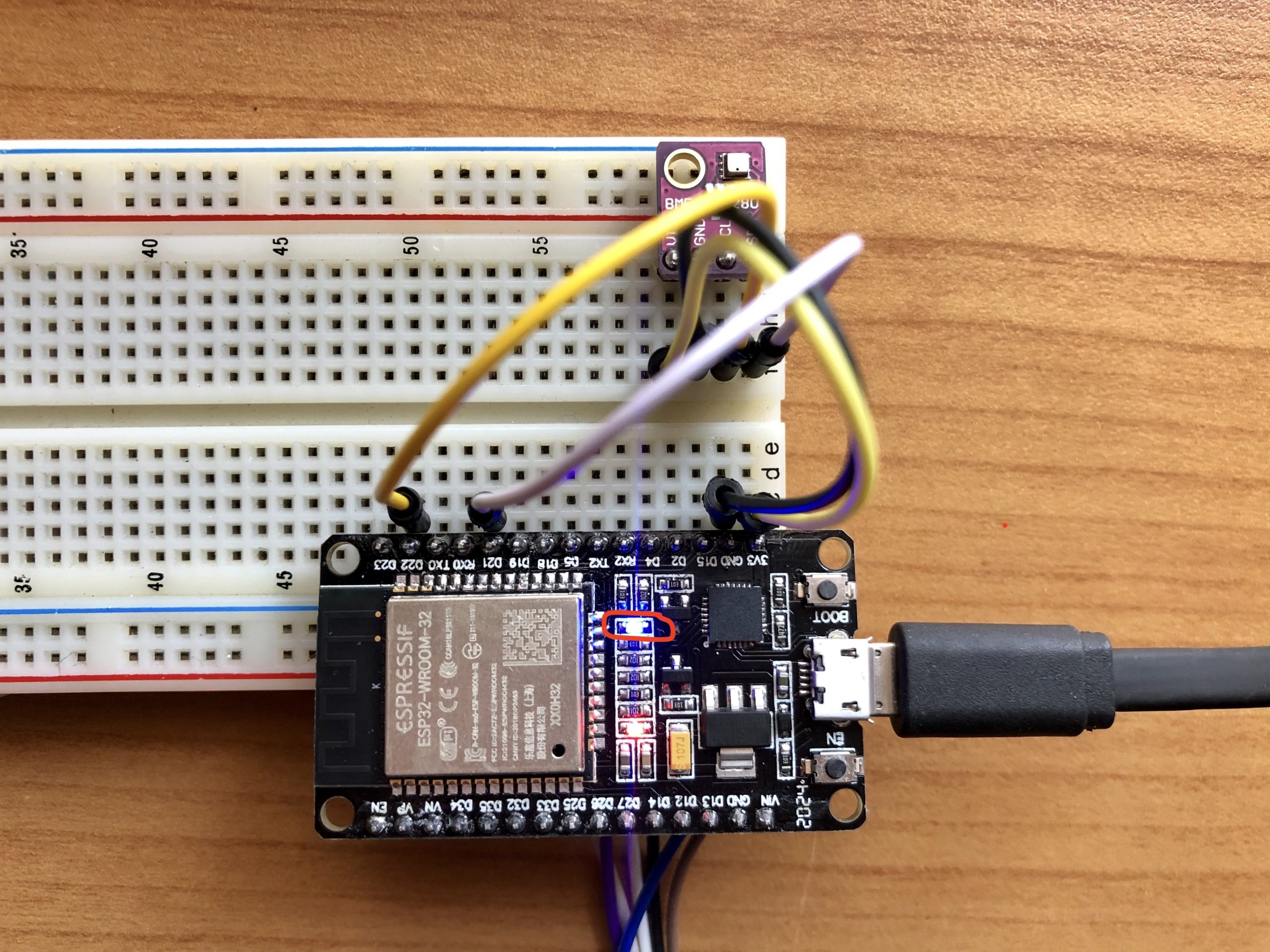
On the image below it is possible to see the status of the LEDs after uploading the software to the devices and in particular of the blue LED. When the blue led is steady on, it means that:
- the connection to the WiFi network was successful;
- the ping to the Message Broker was successful;
- the connection to the EMQ X Edge Message Broker went well;
- the subscription to the topic esp32/command was successful.
Figure 4 - Indication of the operation of the ESP32 device through the blue LED on the development board
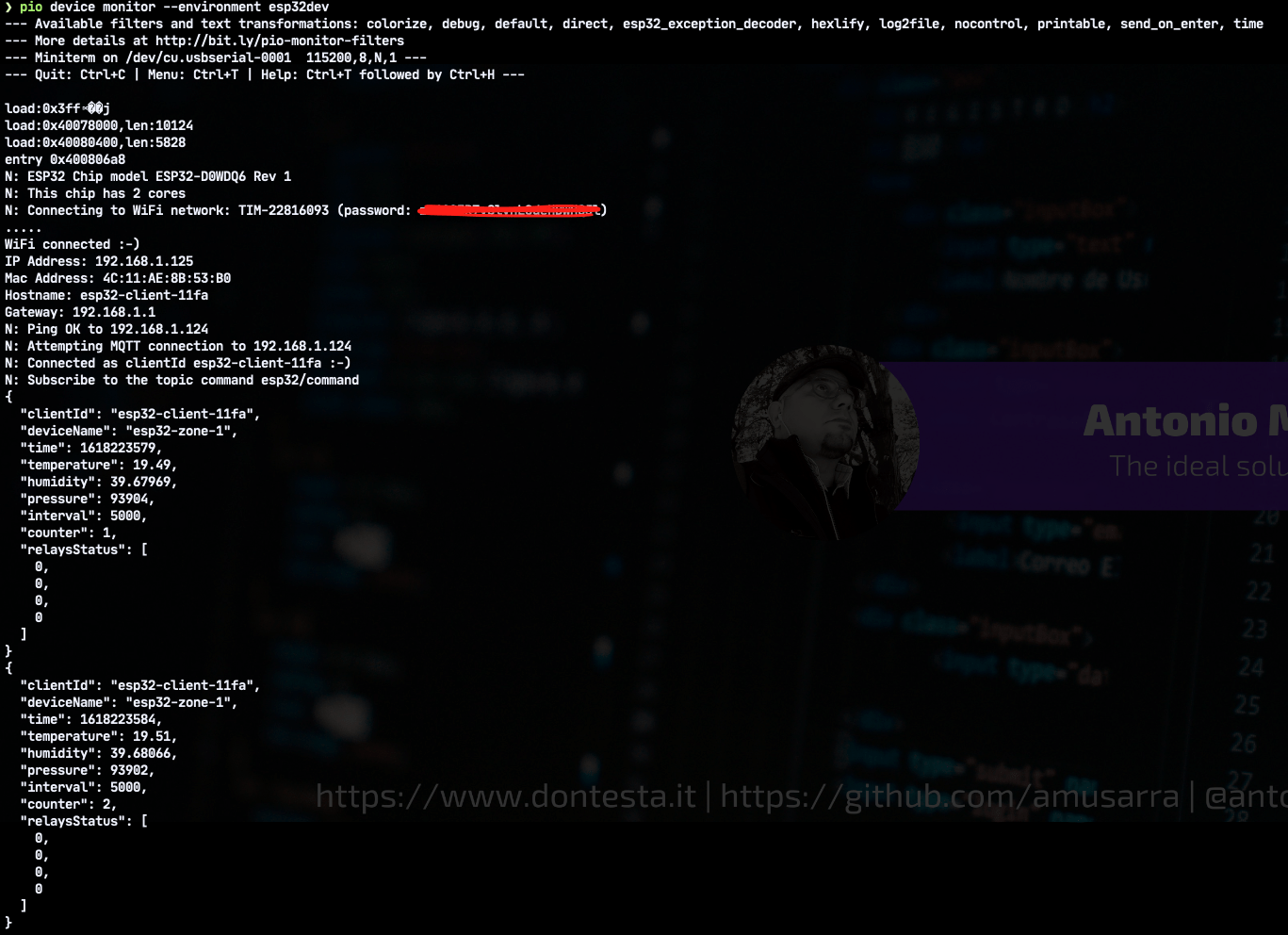
Ultimately this led ( attested on GPIO 2 ) gives us indications if everything is going the right way. In this case we are lucky, the led is on and we are therefore sure that the environmental data are published on the topic esp32/telemetry_data and that the device is ready to receive commands on the topic esp32/command. If we wanted to check the activity of the device, we could connect to the serial monitor always using PlatformIO, using the command: pio device monitor --environment esp32dev
The following image shows the output of the above command. As you can see, we get several information in the output. Information on the chip model, information on the WiFi network to which the device is connected, information on the Message Broker to which the device is connected and finally the JSON published on the topic esp32/telemetry_data.
Figure 5 - Attach of the serial monitor on one of the ESP32 devices in order to monitor the activities in progress
We have to repeat the same software compilation and upload operations also for the second device and once done we can define this phase concluded and go to carry out the first integration test.
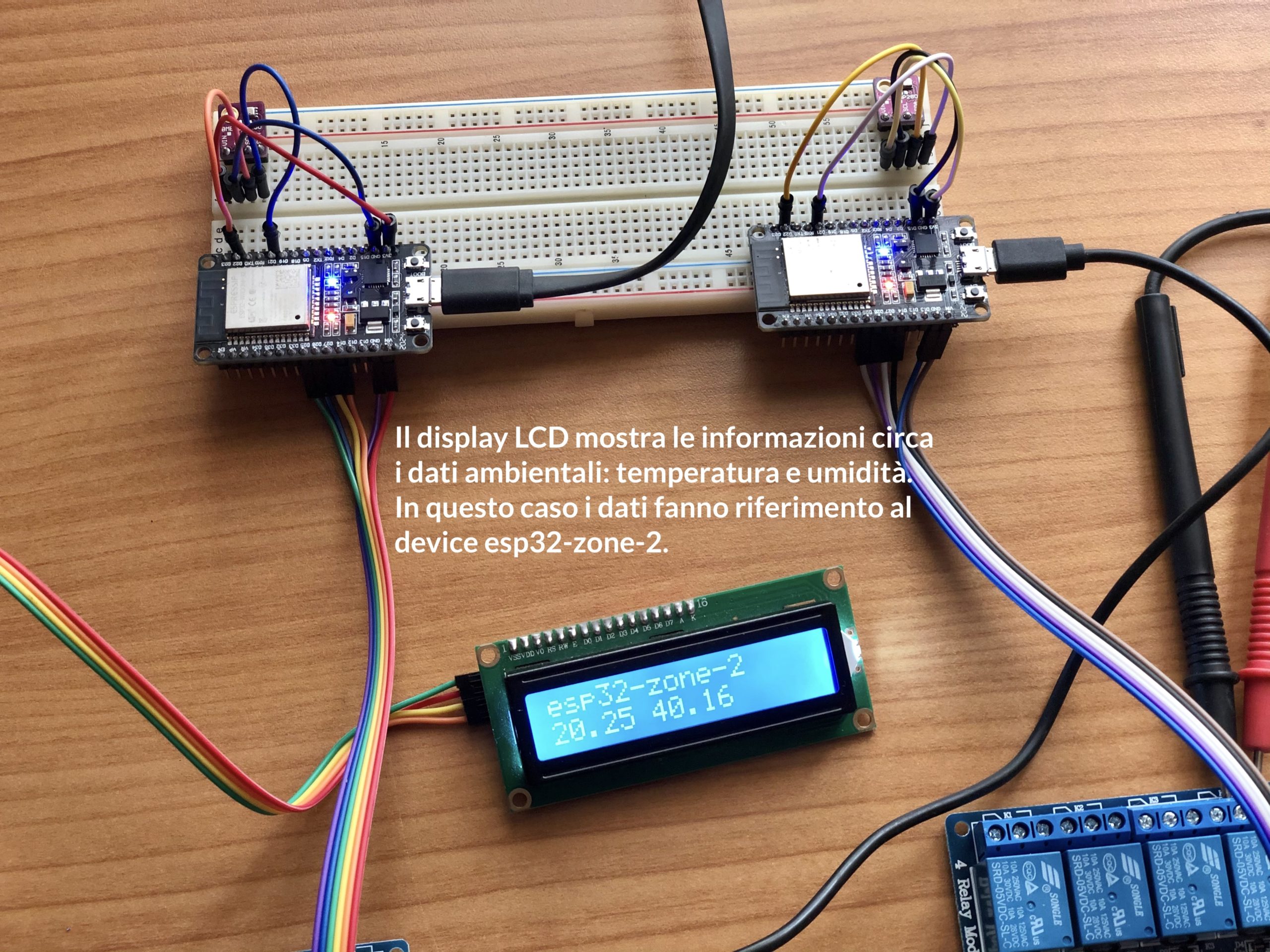
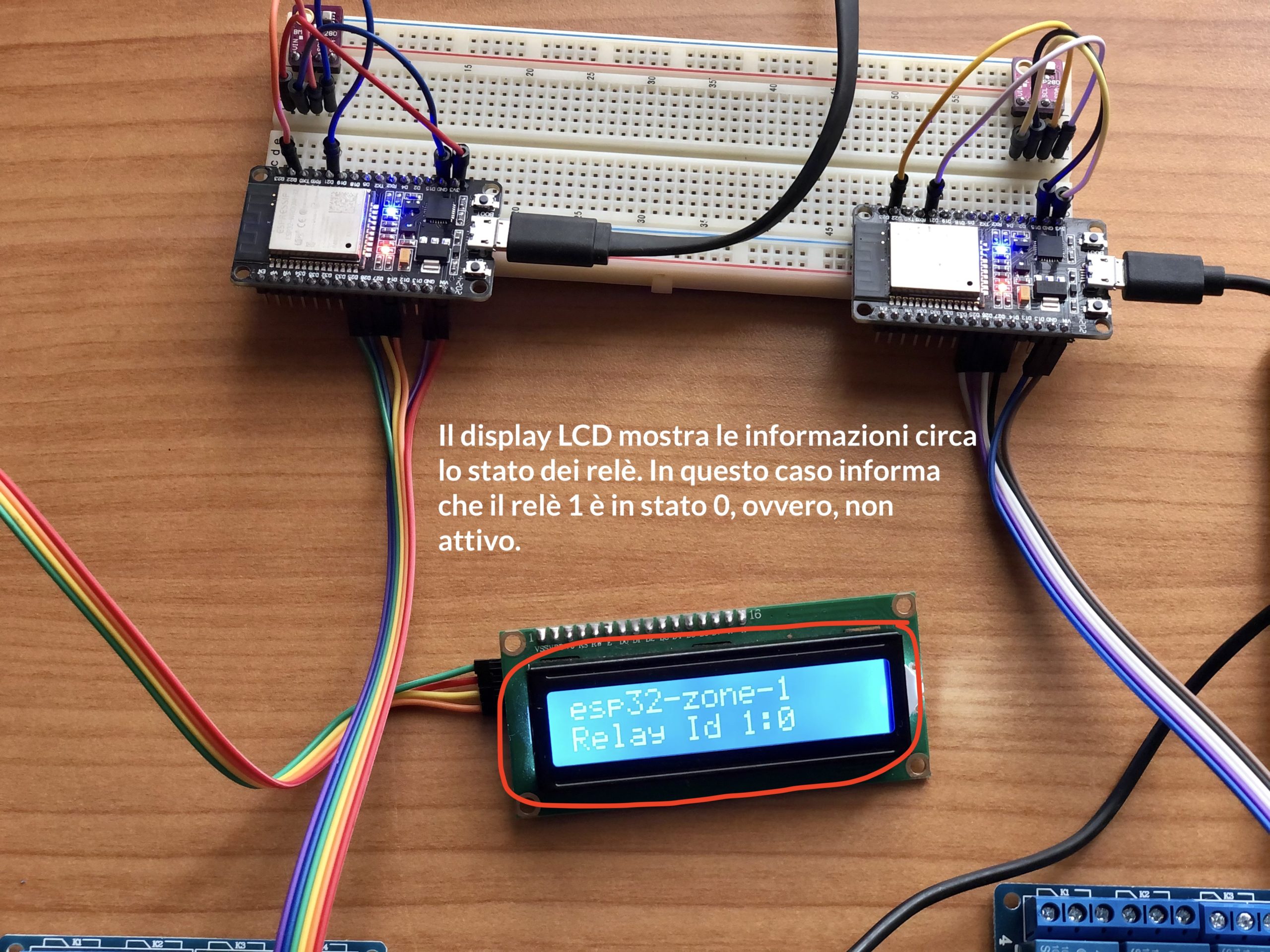
The two images below show the different information that is displayed on the LCD display. The information refers in particular to environmental temperature and humidity data and the status of the relays. The LCD display also shows information on which device is the data source.
Figure 6 - LCD display showing environmental temperature and humidity data for each device
Figure 7 - LCD display showing the status of the relays for each device
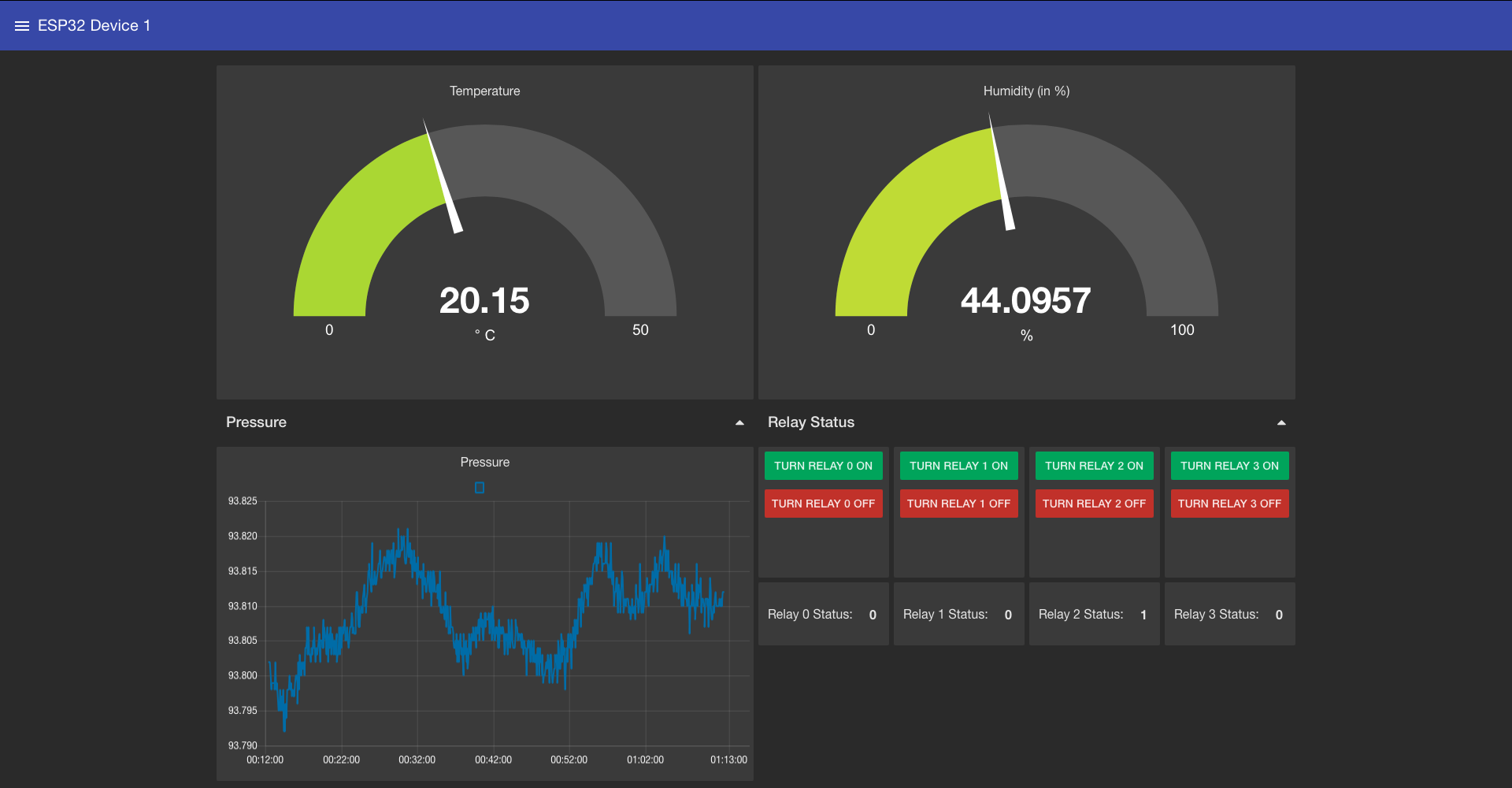
Figure 8 - MQTT Dashboard Node-RED for the ESP32 Device 1


