-
Notifications
You must be signed in to change notification settings - Fork 3
2. Setting up LITOS' hardware
Thomas Höhener edited this page Jan 17, 2023
·
23 revisions

Overview of LITOS' control unit
The control unit of LITOS can be ordered pre-assembled. However, before the first use, you need to connect the PCB with the LED matrix and in a second step load the LITOS software onto the control unit.
- In rare cases, the OLED display might not be already attached to the PCB. In this event, please plug the OLED display into the headers in the middle of the PCB.
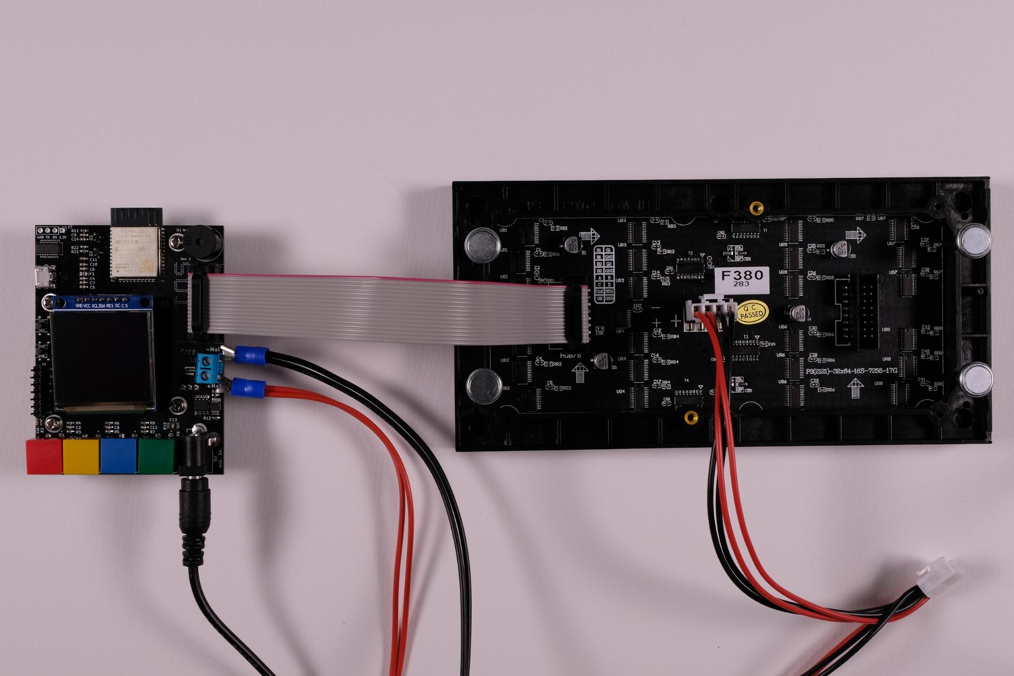
- Connect the flat ribbon cable (16 pins) to LITOS. On the LED matrix, there are two connectors for the flat ribbon cable. Pay attention to connect the cable to the input connector. It is typically located on the left side if the arrows on the back of the LED matrix point to the right and/or to the top.
- Next, connect the power cable to the matrix and the PCB (cable with red / black wire). The red cable end has to be connected to slot 1 (there is also a “M+“ on the PCB) and the black cable to slot 2 (“M-” on the PCB) of the screw terminal. Note: older versions of LITOS have a different screw terminal where only one tine of the fork is screwed.

Connection of power cable to PCB
- Connect LITOS with the wall power adapter.
Now, the software can be loaded onto LITOS (flashing).

Power+Data cable connection between LED matrix and PCB