⚡ Electrical
Note: The Blackbox draws ~1.5-2.5 watts when operating normally.

The Telem 1 port on the Pixhawk 6C includes 6 wires: GND, Tx, Rx, 5V power, CTS, and RTS.

The Power 1 port on the Pixhawk 6C includes 6 wires: 5v, 5v, 3.3v, 3.3v, GND, GND.

The Iridium 9602N has 20 pins, however, only 13 of them are in use: 5v * 2, GND * 5, RX, TX, DTR, RTS, RI
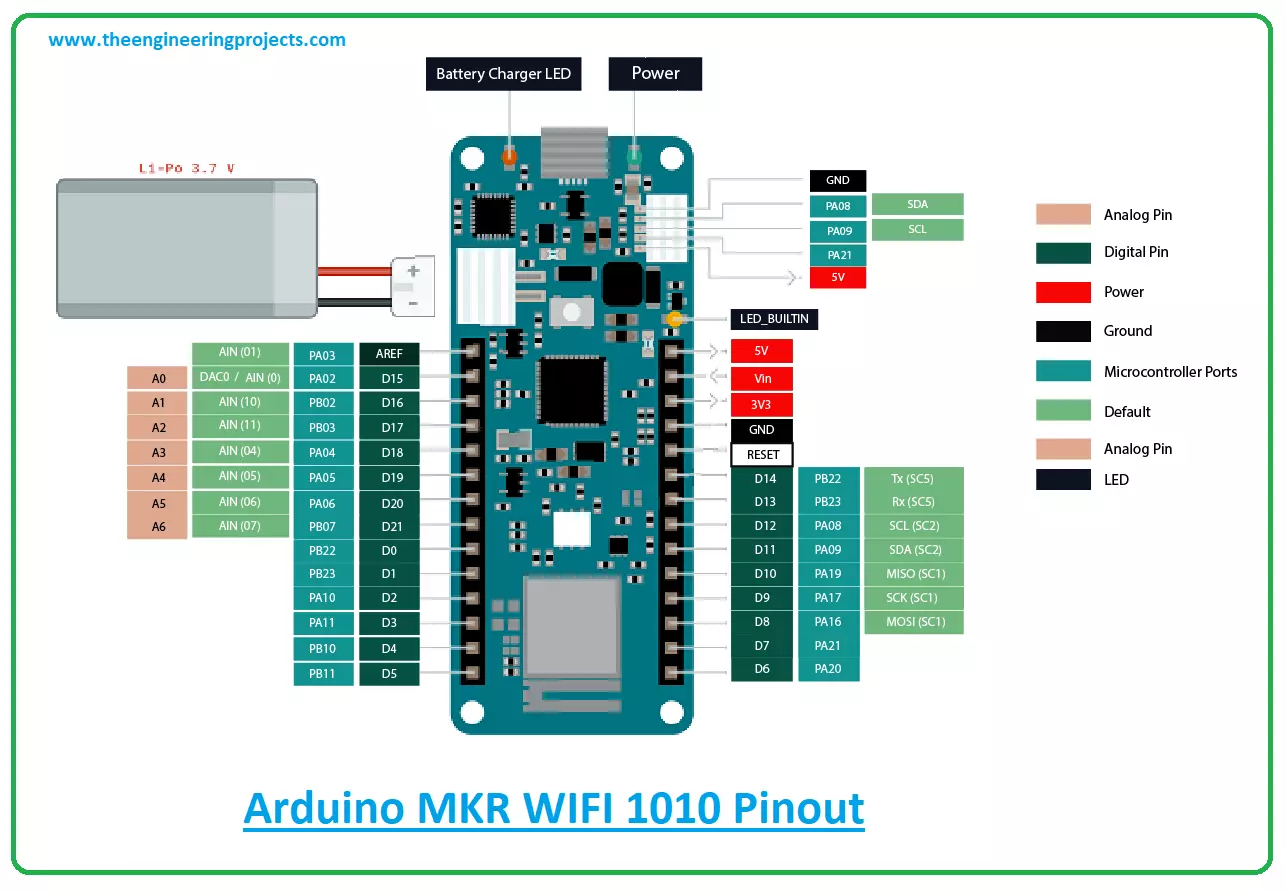
To establish serial communication between the Arduino MKR WiFi 1010 and the Pixhawk 6C using the Telem 1 port, follow these connections:
- Connect the D14 (Tx) pin on the MKR WiFi 1010 to the Rx pin (pin 3) on the Pixhawk 6C's Telem 1 port.
- Connect the D13 (Rx) pin on the MKR WiFi 1010 to the Tx pin (pin 2) on the Pixhawk 6C's Telem 1 port.
To power the Pixhawk 6C, follow these connections:
- Connect pin 1 (5v) to the 5V line of your power supply.
- Connect pin 6 (GND) to the GND line of your power supply.
To establish serial communication between the Arduino MKR WiFi 1010 and the Iridium 9602N modem, follow these connections:
- Connect the D0 (Tx) pin on the MKR WiFi 1010 to the Rx pin (pin 6) on the Iridium 9602N.
- Connect the D1 (Rx) pin on the MKR WiFi 1010 to the Tx pin (pin 7) on the Iridium 9602N.
- Connect the D2 (GPIO) pin on the MKR WiFi 1010 to the RTS pin (pin 13) on the Iridium 9602N.
- Connect the D3 (GPIO) pin on the MKR WiFi 1010 to the DTR pin (pin 14) on the Iridium 9602N.
- Connect the D4 (GPIO) pin on the MKR WiFi 1010 to the sleep pin (pin 5) on the Iridium 9602N.
- Connect the D5 (GPIO) pin on the MKR WiFi 1010 to the ring pin (pin 12) on the Iridium 9602N.
To power the Iridium 9602N, follow these connections:
- Connect The GND line of your power supply to pins: 3, 4, 8, 15, and 18 on the Iridium 9602N.
- Connect the 5V line of your power supply to pins: 1 and 2.
To power the Arduino MRK WiFi 1010, follow these connections:
- Connect The GND line of your power supply to the GND pin on the Arduino MKR WiFi 1010.
- Connect the 5V line of your power supply to the VIN (not the 5v output!) pin on the Arduino MKR WiFi 1010.
To connect the diagnostic RGB LED to the Arduino MKR WiFi 1010, follow these connections:
- Connect the GND line of the LED to the GND line of your power supply.
- Connect The RED line of the LED to pin 7 on the Arduino MKR WiFi 1010.
- Connect The GREEN line of the LED to pin 8 on the Arduino MKR WiFi 1010.
- Connect The BLUE line of the LED to pin 9 on the Arduino MKR WiFi 1010.
