-
Notifications
You must be signed in to change notification settings - Fork 18
Hydraulic 2D structure
Available since experimental version 2.2.90
Hydraulic 2D structure are a hydraulic network element that represent a complete flow 2D model. As a part of a hydaulic network, its boundary conditions can be connected to other part of the network by hydraulic network link.
To create a new Hydraulic 2D Structure, the user has to select the map tool "Structure 2D":
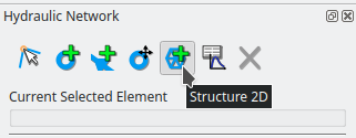
With this tool, the user has to delineate the domain of the model by digitizing on the map. Note that a right click on an existing vector layer polygon feature allow the user to defined the domain by this polygon.
The entry to Hydraulic 2D Structure is through the properties window of this element (see Hydraulic network).
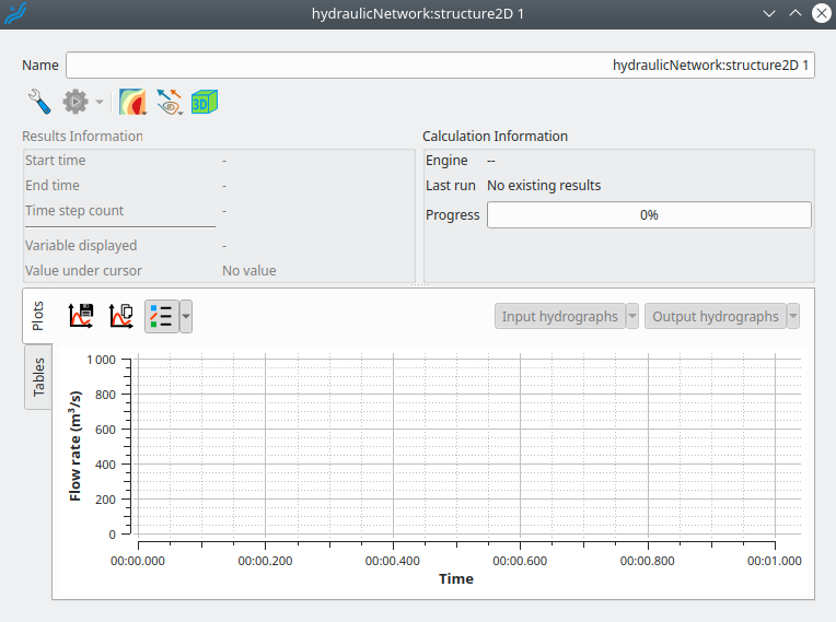
The tool buttons on top right of the window under the name parameter allow the user to (from left to right):
- Enter in the window to edit the flow model,
- Launch simulation, export simulation, or change settings of the simulation engine
- Change settings of scalar rendering on the map: selection of the variable, color ramp settings and mesh frame settings
- Change settings of vector field rendering: selection of the variable and vector displaying settings
- Open the 3D view.
Once entered in editing, several pages allow the user to edit the flow model. The different pages can be chosen from the list on the left on the window. These pages are:
-
Structure: editing of the structure lines, holes, boundary conditions, and mesh generation algorithm choice.
-
Mesh Resolution: drawing of polygon associated with mesh element sizes, allowing the user to vary the resolution of the mesh.
-
Topography: handling Digital Elevation Models to drap topographies on the mesh.
-
Edit elements / Mesh quality: mesh elements editing and mesh quality checking.
-
Roughness: drawing of polygon associated with roughness value, allowing the user to vary the roughness of the flow model.
-
Simulation Configuration: choosing the simulation engine and simulation settings.
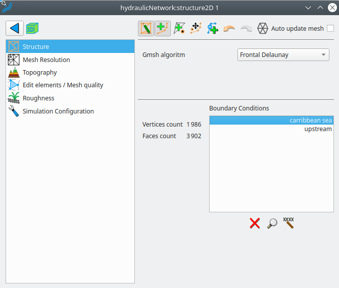
Use of buttons on the top of the page:


On this page, the user can also choose the algorithm to generate the mesh.
At the bottom, below the boundary condition box, buttons allow the user to delete or rename a boundary condition, or to zoom in on it (all after selecting it in the list).
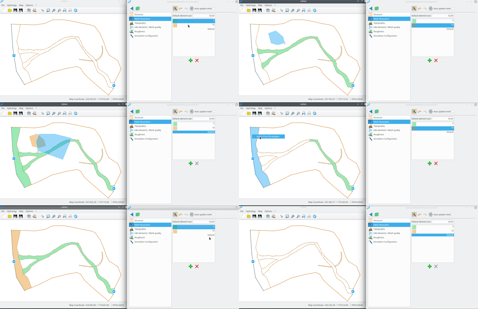
On this page, the user can draw polygons that are associated with element size values. User can add/remove size classes, and then after selecting a class, draw a polygon of this class. When generating a mesh, the algorithm will use the size value of polygon classes to adapt the mesh element sizes.
The button 
A right click on a closed polygon defined by structures lines or by vector layer feature allows the user to directly use this polygon to draw a new mesh resolution polygon with the selected class.
To remove a polygon or a part of it, just select the "Default" class and draw a polygon including all the polygon to removed it or a part of it.
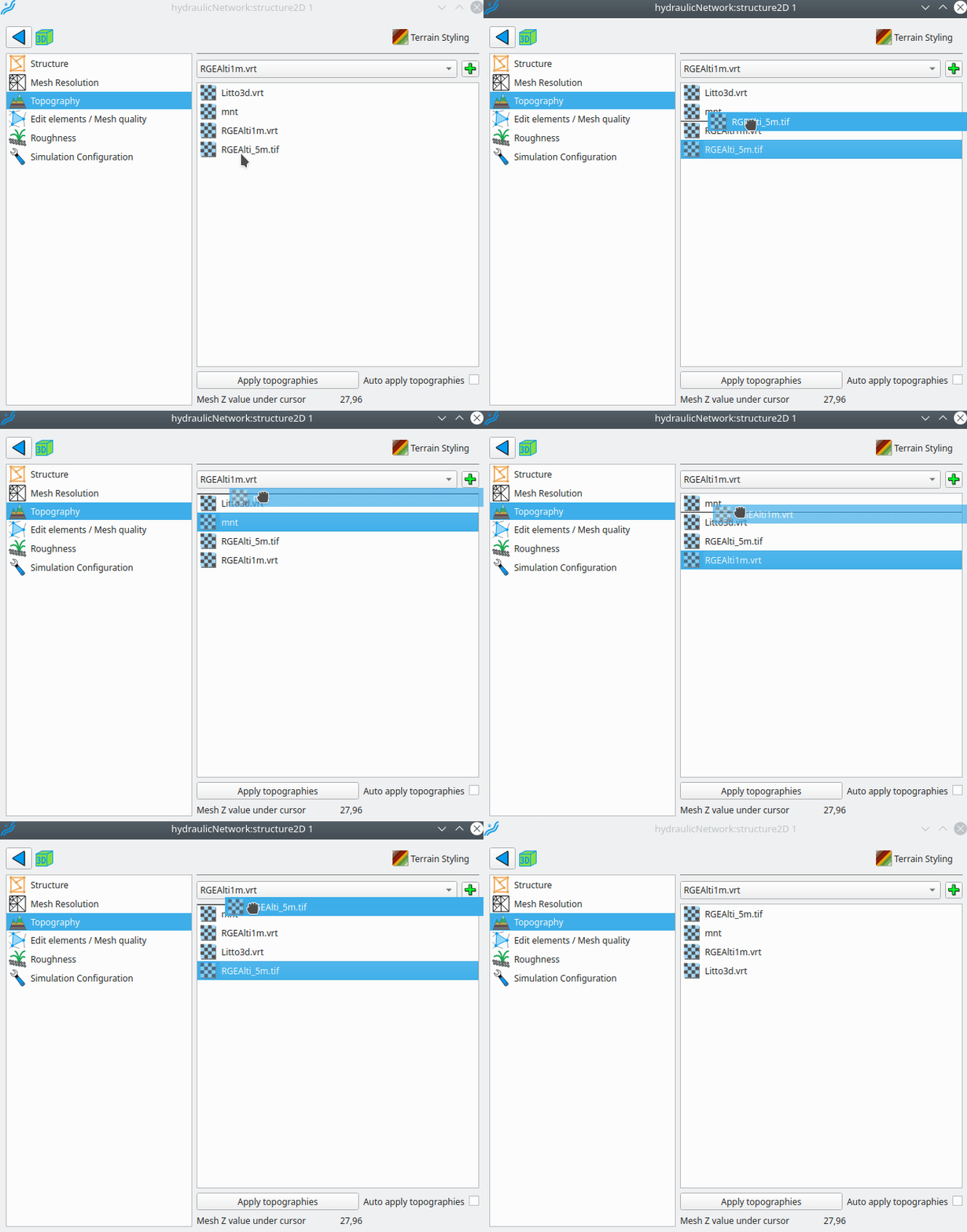
Elevation values of mesh vertices are deduced from DEM layer(s).
All DEM layers registered in the project are present in "Available DEM", and user can choose which ones to apply on the mesh. When there are more than one layer chosen, the order can be changed by selecting one layer and dragging it to the desired location.
Clicking the "Apply" button leads to drap all the layers on the mesh following this way: for each vertex, if the first DEM layer has a valid value a the position of the vertex, this value is set to the vertex. If not, the second DEL layer is considered, if there is no valid value on the second DEM at the position of the vertex, the third DEM layer is considered, and so on.
Note that the rendering style of elevation of the mesh can be changed after clicking the button "Terrain Styling" on the top of the page.
On this page, it is possible to elements of the mesh, that is:
- move/delete vertices
- flip faces
- change Z value of vertices
On the top of this page, the button 
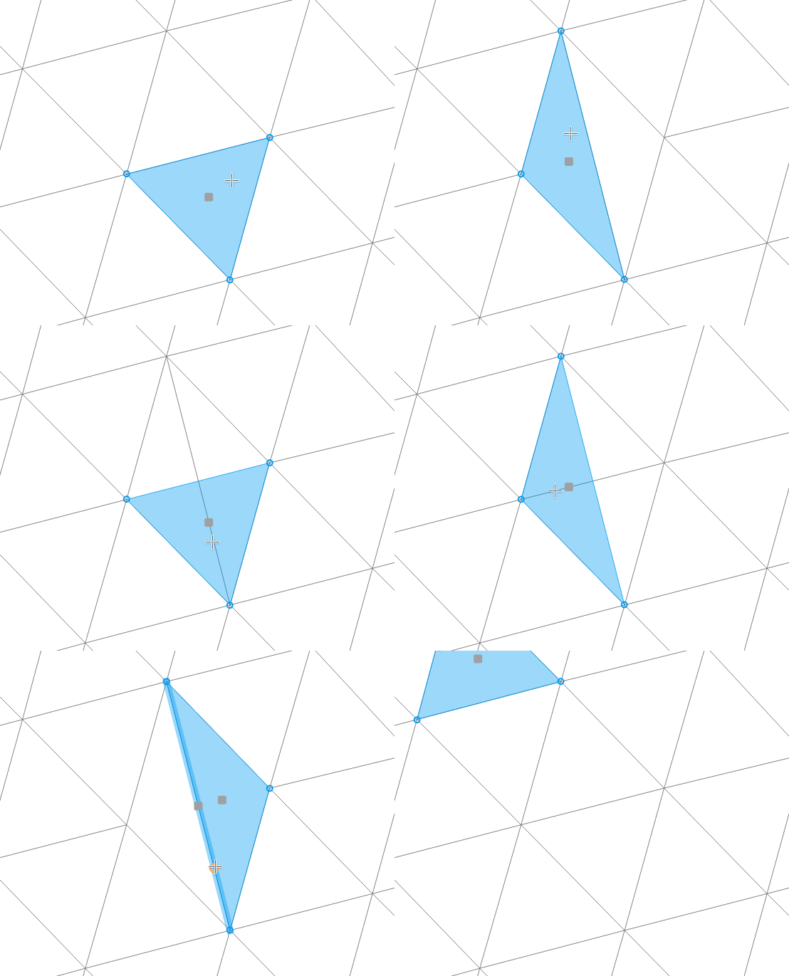
To flip two faces, the user can click on the circle that appear on the edge when the mouse cursor hover it.
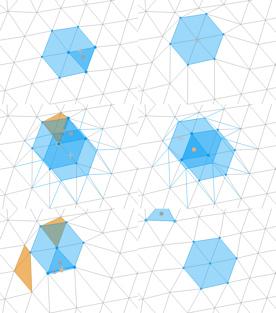
For selecting vertices, user can:
- select vertex by left clicking on it
- select vertices by dragging a rectangle
- select all vertices of a face by clicking the square on the middle of a face
- select the two vertices of an edge by clicking the quare on the middle of an edge
- select vertices by drawing a polygon after a switch with the button
on the top of the page
For selecting by rectangle or by polygon, default behavior select all the vertices's of intersected faces. To select only the contained vertices, user has to press Alt key during selection.
Once selected, vertices can be moved by clicking on a selected vertex, or on the square of faces/edges. This first click defined the starting point of the move as the position of the vertex, or the middle of face/edge. The ending point is defined by a second click.
Selected vertices can be removed or have their Z value changed by right click or using the buttons on the top of the page.
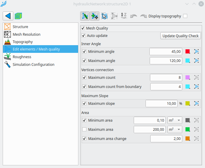
When the user is on this page, the quality checking is activated. Each mesh element that does not respect one criteria defined on this page leads to highlight this element on the map. Each criteria is associated with a color that can be changed by the user. Pressing buttons 
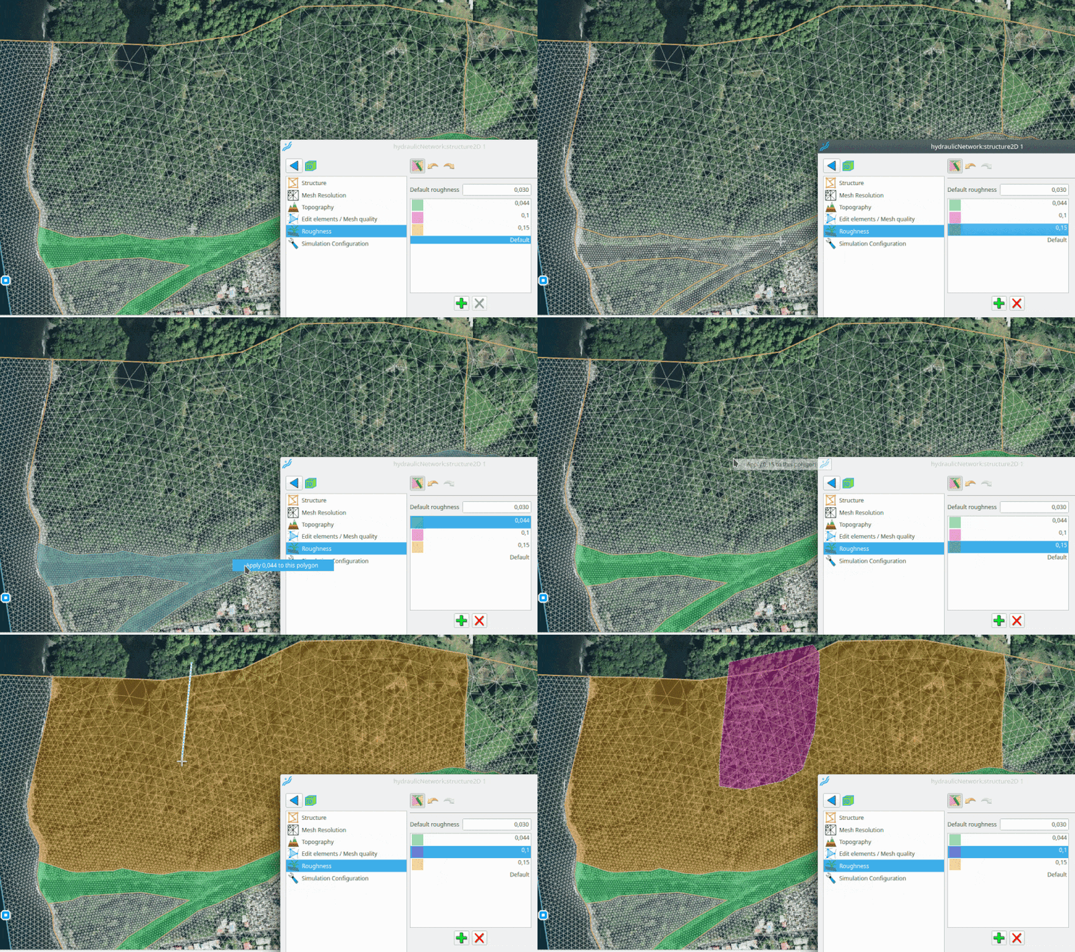
On this page, the user can draw polygons that are associated with a roughness values (Manning's coefficient). User can add/remove size classes, and then after selecting a class, draw a polygon of this class.
The button 
A right click on a closed polygon defined by structures lines or by vector layer feature allows the user to directly use this polygon to draw a new roughness polygon with the selected class.
To remove a polygon or a part of it, just select the "Default" class and draw a polygon including all the polygon to removed it or a part of it.
On this page, the user can handle different simulation configurations. The first step is to add an new configuration with the button 
For the TELEMAC 2D solver, parameters are described below.
- Time step: time step use by the solver
- Output period of 2D results: number of time step between two 2D result dataset that will be recorded.
- Output period for hydrograph: number of time step between two hydrograph values that will be recorded
The user can choose following initial conditions types:
- Constant water level, no velocity: a constant static water level is apply on the whole mesh at the start of the simulation.
- From other hydraulic scheme: all the variable at the start of the simulation come from a result of another simulation of the same model run in another hydraulic scheme
- Interpolation line: for the whole mesh, static water level values interpolated from two values at the ends of a line drawn on the map, as in the following diagram:
- equation scheme use by the solver : Finite Element or Finite Volume
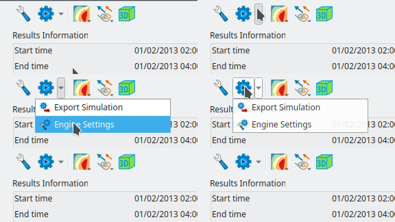
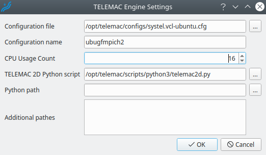
To run TELEMAC simulation from Lekan, it is necessary to setup information in the following window:
If the TELEMAC configuration does not support parallelization, the CPU Usage count has to be set to 1.
This is a side bar
