As part of building a new desk, I was going to have a small cabinet with my desktop computer and other possible heat-producing devices in it. To prevent it from getting too hot in there, I decided to build a fan controller so that the fan speed would be automatically adjusted depending on the temperature.
Because I've already had some experience with it, I decided to use an Arduino for this. I'm using the Adafruit ItsyBitsy 32u4 5v. This code can probably be easily adapted for other ATmega32u4-based Arduinos (Leonardo, etc), and with a little bit of work can probably be made to work with other AVR-based Arduinos as well. Outside of those, it'll be quite a bit harder as there's a lot of AVR-specific register usage:
-
The
Fanclass configures PWM and external interrupts directly. For other AVR boards, the interrupt specific code will probably work as-is, but the timer/PWM code will need to be updated to match that controller's specific Timer/Counter configuration and capabilities. -
The
Thermometerclass is able to use the AVR-specific internal temperature sensor. It's not a very good sensor, as it's uncalibrated by default (and can be off by 10 °C). If using an external sensor (I'm using a TMP36), you can safely remove all the internal sensor blocks. -
Settings::saveuses the EEPROM and optimized CRC16 functions provided by avr-libc, but these can be pretty easily modified to use other functions. -
The
Menuclass stores some longer strings in Flash using theF()macro, which might not be portable to non-AVR platforms.
A KiCad schematic is included in CabinetFan.sch, as well as an SVG version:
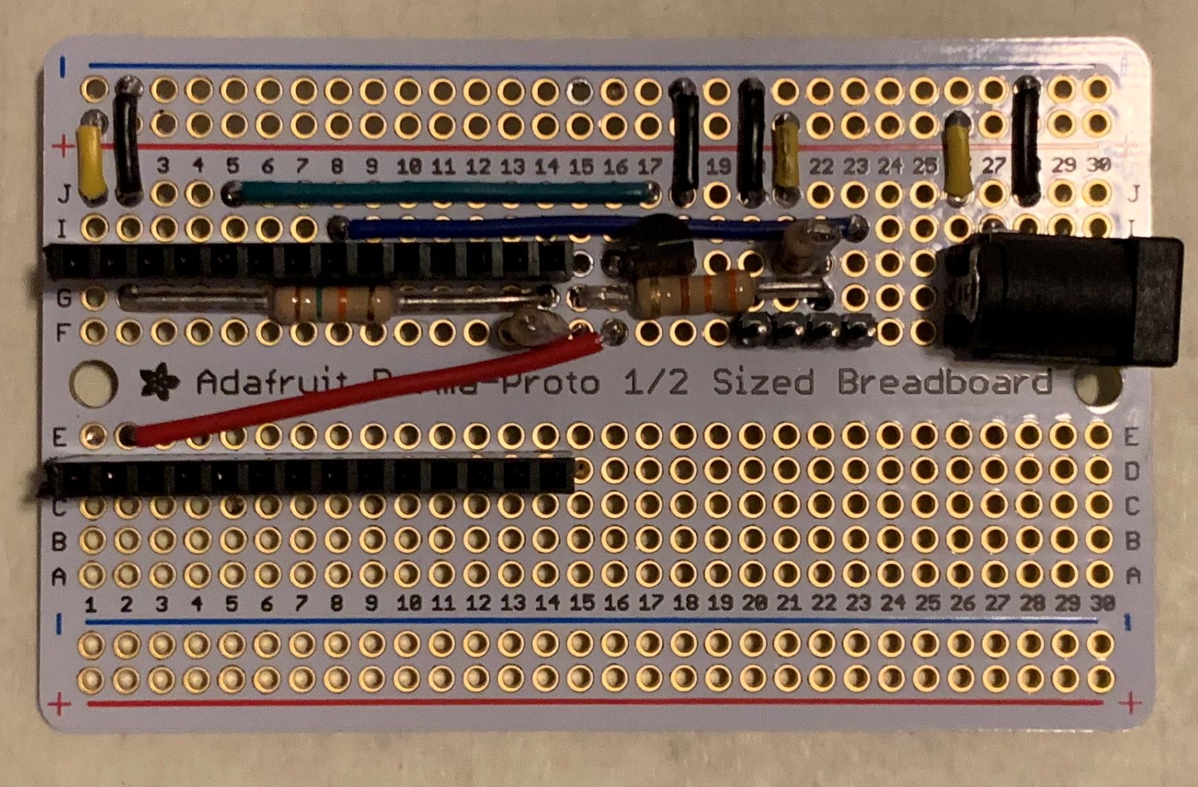
Here's a photo of my finished board:
The ItsyBitsy is inserted into the socket with the USB port to the left. The fan is plugged in with in with an imaginary key slot towards the bottom of the board. A 12V, center positive AC-DC adapter is attached to the barrel plug on the right. It's not super clear, but there is a TMP36 on columns 16-18, row H. The 10k resistors are mounted vertically.
