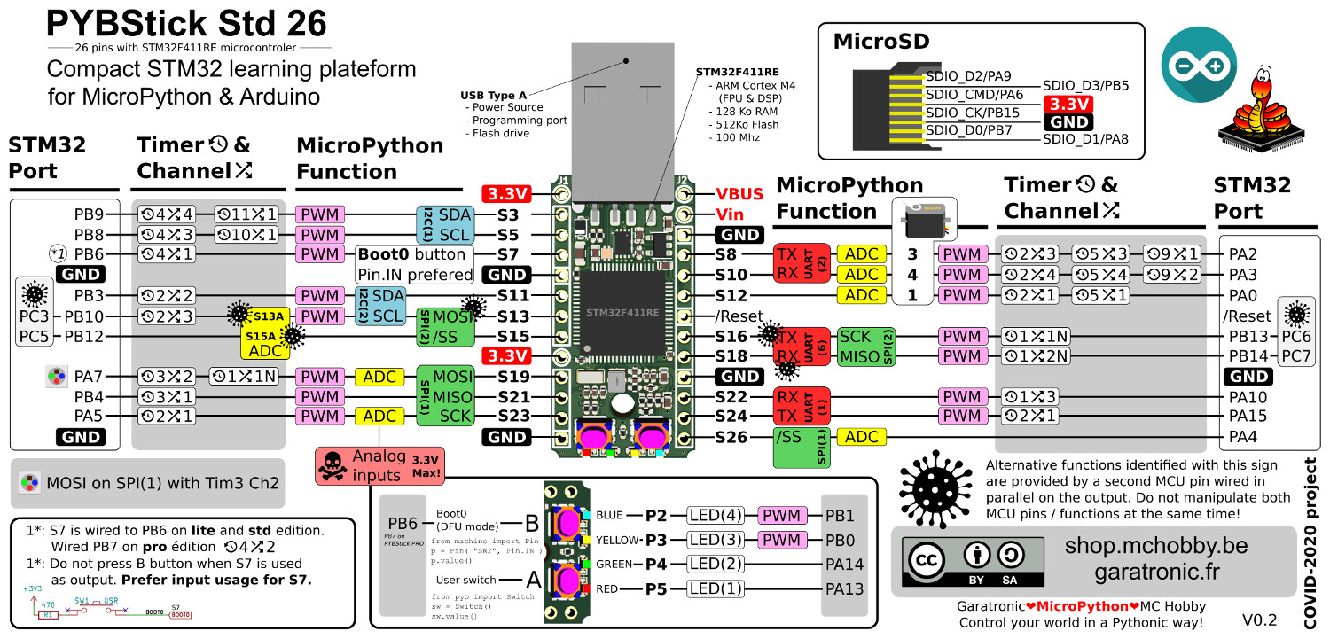
The board used in this community contribution is a STM32F411RE based board from MCHobby and Garatronic.
This board has multiple functions and they are pre setup like this in the picture.
Please note that only SPI1 is pre setup, the 2 I2C are available, all ADC can be used. Only UART2 (RX PA3, TX PA2) is setup.
Here are the corresponding pin number for ADC:
- S8 = PA2 = ADC1 channel 0
- S10 = PA3 = ADC1 channel 1
- S12 = PA0 = ADC1 channel 2
- S26 = PA4 = ADC1 channel 3
- S23 = PA5 = ADC1 channel 4
- S19 = PA7 = ADC1 channel 5
- Temperature (not accurate) = ADC1 channel 6
- Reference voltage (1.21 V) = ADC1 channel 7
- Battery voltage =ADC1 channel 8
Pins for SPI1:
- S23 = PA5 = Clock
- S21 = PB4 = MISO
- S19 = PA7 = MOSI
- You can use any chip select. S26 = PA4 is a hardware one
Pins for I2C1:
- S3 = PB9 = SDA
- S5 = PB8 = SCL
Pins for I2C2:
- S11 = PB3 = SDA
- S13 = PB10 = SCL
Pins for UART2 = COM2
- S8 = PA2 = TX
- S10 = PA3 = RX
Pins for PWM:
- S8 = PA2
- S10 = PA3
- S12 = PA0
- S16 = PB13
- S18 = PB14
- S3 = PB9
- S5 = PB8
- S7 = PB6
- S19 = PA7
- S21 = PB4
- Note: none of the TIM2 pins are activated