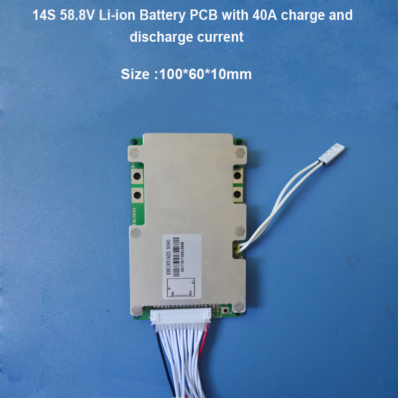
Want to access all that juicy battery data from your BMS without having to use computer software to read the info? Want to display all that data on an Arduino driven LCD or OLED? You have come to the right place.
This is an Arduino library that communicates data from Generic Chinese BMSs. Might work with:
- BMSs from lithiumbatterypcb.com aka LLT Power
- 'Xiaoxiang' BMS
- Some BMS's Labelled "Smart BMS"
It is probably going to work. Mine was a 21s so it had two of the 16 pin JST connectors at the base. All cell counts should work. You can always check if the UART protocol matches the protocol linked at the bottom of the page.
- Wire your BMS to the cells and to the load as normal.
- Connect the Arduino
- Connect the ground of the arduino to the ground of the BMS
- Connect the RX and TX to any two pins on the Arduino
- DO NOT CONNECT THE FOURTH PIN TO VCC. You may connect this pin (which supplies ~10.5 volts) to VIN if you wish to power the Arduino from the BMS.
Just copy the example code!
- Set the number of cells with "#define NUM_CELLS"
- Set the number of temperature probes with "#define NUM_TEMP_PROBES"
- Create a Software Serial object.
- Inside void setup(), begin the Software Serial port at 9600 baud.
- Inside void setup(), pass the software serial object to the BMS object.
#define BMS_RX_PIN 2 //pin the bms is reciving signals on, where we are sending.
#define BMS_TX_PIN 3 //pin the BMS is sending signals to, where we are recieving.
#define NUM_CELLS 21
#define NUM_TEMP_PROBES 4

#include <SoftwareSerial.h>
#include <BMS.h>
SoftwareSerial BMSSerial(BMS_TX_PIN, BMS_RX_PIN);
BMS bms;

void setup() {
    Serial.begin(115200);

    BMSSerial.begin(9600);
    bms.begin(&BMSSerial);

    Serial.println("Finished setup");
}- Call "bms.update()"
- Call the appropriate methods to return the relevant data:
float *getCells() { return cells; }
uint32_t getBalanceState() { return balanceState; }
float getPackVoltage() { return packVoltage; }
float getPackCurrent() { return packCurrent; }
float getCellMaxVoltage() { return cellMax; }
float getCellMinVoltage() { return cellMin; }
float getCellDiff() { return cellDiff; }
byte getNumProbes() { return NUM_TEMP_PROBES; }
float *getProbeData() { return probes; }
MOSFET_STATUS getMOSFETStatus() { return MOSFETStatus; }
Note about using the MOSFETStatus struct: just do "bms.getMOSFETStatus().discharge" to get whether discharge is permitted and "bms.getMOSFETStatus().charge" to get whether charger is permitted.
Sources and Helpful Links
- Another Smart BMS Reader designed for a similar purpose. I would have used this version if it had been in the traditional Arduino Library format (import, instantiate, start, call methods...), or easier to understand.
- My copy of the spreadsheet defining the BMS Protocol that explains the protocol and how to communicate with the BMS. I also color coded one of the responses so you can see what bytes mean what.
- Any other information you might ever need plus a TON of helpful links that I won't duplicate.
